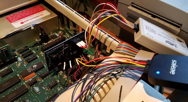
After a month of inactivity, I finally returned to my unfinished Yellowstone disk controller project to investigate the JTAG programming problems. Yellowstone is an FPGA-based disk controller card for the Apple II family, that aims to emulate a Liron disk controller or other models of vintage disk controller. It’s still a work in progress.
Last month I discovered some JTAG problems. With the Yellowstone card naked on my desk, and powered from an external 5V supply, JTAG programming works fine. I can program the FPGA to blink an on-board LED. And when I insert the already-programmed card into my Apple IIe and power it from the slot, it works – the LED blinks. But if I try to do JTAG programming while the card is inserted in the IIe, it always fails with a communication error. I’ve run through several theories why:
- It might be some kind of noise or poor signal integrity on the JTAG traces. But the traces are quite short and don’t cross any other signal traces that might carry interfering signals.
- Maybe I have power problems, and the IIe’s 5V supply is drooping briefly when I try to program the FPGA via JTAG. But I measured the 5V and 3.3V supply voltages during JTAG programming, and they look fine.
- There might be a ground loop, due to the Apple IIe and JTAG programming having different ground potentials. But I measured the difference in grounds, and it’s only 4.3 millivolts.
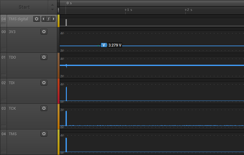
To help solve this mystery, I used the analog mode of my Saleae Pro 8 Logic analyzer. In analog mode, it functions like a simple 8-channel 12.5 Ms/sec oscilloscope. I recorded the 3.3V supply for the FPGA, as well as all the JTAG signals. First, here’s what the first three seconds of JTAG traffic look like when programmed externally:
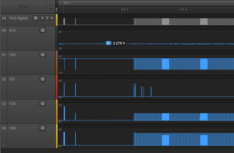
There’s about 1 second of preamble communication, and the rest is the FPGA configuration data arriving at high speed. The 3.3V supply for the FPGA remains at about 3.28V through the whole process. The JTAG signals TMS, TDI, and TDO span the voltage range from 0.17V to 3.2V, which seems fine. But the the TCK signal never goes higher than 1.86V. Uh oh, what’s happening there? Let’s zoom in a little:
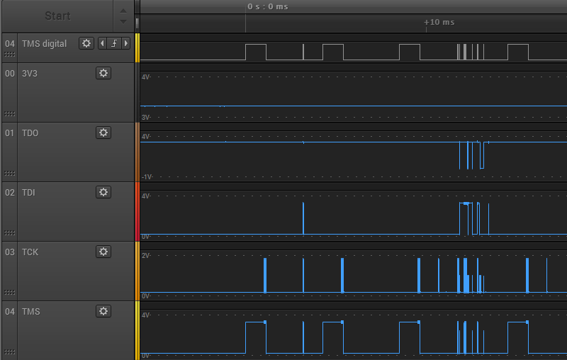
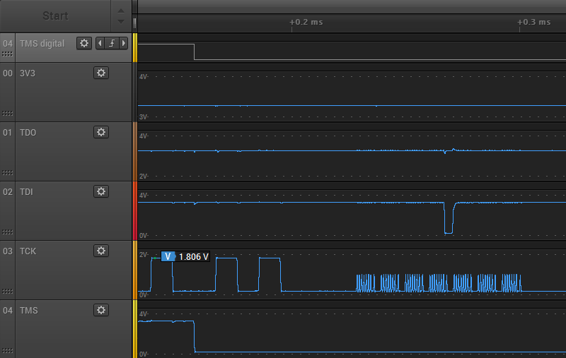
Zooming in, things are even worse than they appeared initially. TCK never climbs above 1.86V, but many TCK pulses only get half that high, stopping at 0.97V. TMS and TDI show some runts too. Zooming in even further on one of the problem areas:
Here you can see a couple of the 1.86V TCK pulses, followed by a whole mess of the runtier 0.97V pulses. Ugh. These should all be using the full range 0 to 3.3V, or something close to it. With a clock signal this bad, it’s amazing the JTAG programming still works.
Do these graphs really reflect what’s happening? I’m a little suspicious that I’m running into limitations of the Saleae Pro 8’s analog mode. At 12.5 Ms/sec, it’s taking one analog sample every 0.08 microseconds or 80 nanoseconds. That’s pretty poor as scopes go, but the period of the JTAG clock is slow: about 1 microsecond (1 MHz operation). There should be 12.5 samples per clock period, more than enough to get a decent reading for the min and max voltage of each clock period. Therefore I think the graphs are accurate.
My conclusion is that although external JTAG program succeeds, the JTAG signals look terrible. The fact that JTAG programming fails when the card is in the Apple IIe slot likely has little to do with the IIe, and everything to do with some other basic signal quality problem.
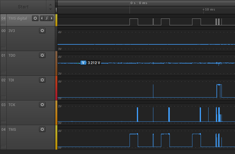
Next I put the Yellowstone card into the Apple IIe, and repeated my test. Here’s the first three seconds of JTAG traffic again:
There’s a short bit of preamble communication, then nothing. Something must go wrong at the beginning, and the rest of the communication is aborted. The voltage levels all look about the same as when programming externally. The 3.3V supply is about 3.28V, TCK never goes higher than 1.86V, but the other JTAG signals use the full voltage range. Zooming in, we observe the same extra-runty TCK pulses as with external JTAG programming:
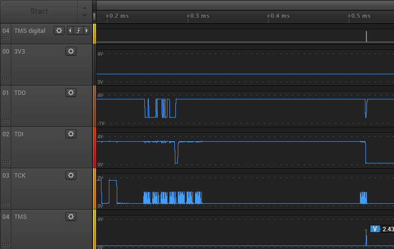
It’s not obvious to me why external JTAG programming succeeds, but programming in the Apple IIe slot fails. Both cases look equally bad. The only real difference I noticed is the TDO signal. In the case of external programming, the TDO high voltage is very steady at about 3.268 volts, and never varies by more than 0.01V. It also drops low at many points during the JTAG communication. But in the case of in-slot programming, the TDO signal is always high and the voltage is noisier. It’s a subtle difference, but you can see the minor noise here:
The TDO high voltage ranges from 3.187V to 3.314V, so it’s about 10x noisier than during external programming. It’s still within an acceptable range though, so maybe this isn’t important.
Finding the Culprit
Now that I know I have poor quality JTAG signals, where do I look for the cause? Poor quality JTAG programmer? Bad PCB design? Here’s a section of the PCB, showing the path of the JTAG signals from the connector to the FPGA:
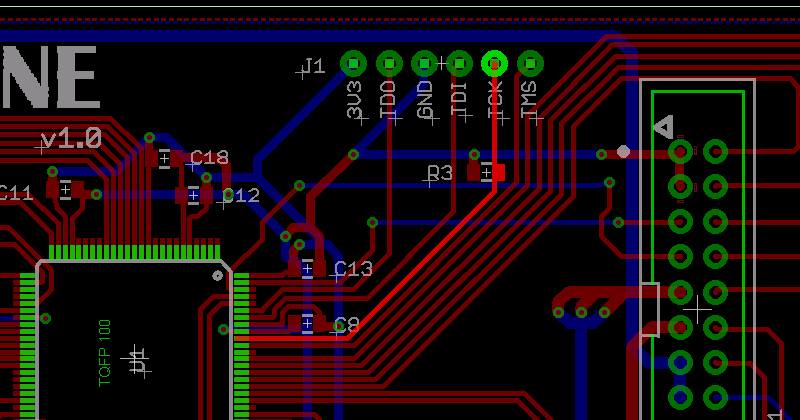
There’s not much opportunity for interference. The only PCB tracks that are crossed by the JTAG signals are voltage supplies and the disk I/O signals, which were unconnected during this test.
The prime suspect is R3, a 4.7K pulldown resistor on TCK. This was recommended by Lattice, as a precaution to prevent spurious TCK pulses causing unwanted JTAG activity when no JTAG programmer is present. Lattice technote TN1208 for the MachXO2 family says on page 12-2 “TCK: Recommended 4.7kOhm pull down.” The other JTAG signals discussed here all have internal pull-ups. 4.7K isn’t much, but maybe the JTAG programmer has an anemic drive strength and is unable to drive TCK fully to 3.3V with the pulldown present? I could try removing R3, but that wouldn’t explain why there are also some runt pulses seen on TMS and TDI. I double-checked to confirm I didn’t accidentally use the wrong value resistor for R3, but no: it’s 4.7K as intended. I also measured the resistance between TCK and GND, to see if there’s some other unintended low-resistance path to GND that’s screwing up everything, but it measured 4.7K exactly.