There’s a big difference between building one of something, and building a hundred. When building one, the challenge is simply to get the thing working at all. When building a hundred, the focus changes to issues like how fast you can do the build, and how reliably. Little problems that only crop up rarely start to become headaches. And if you’re like me, you start to get obsessed with achieving 100% reliability without sacrificing build speed or cost.
With Floppy Emu now past the 100 units mark, I can start to get some meaningful data from the assembly process. Thus far slightly more than 90% of the units I’ve built passed all my tests, and were able to be sold. Even for a hand-built piece of hardware, that’s not great. Getting closer to 100% yield will require troubleshooting what went wrong, and making sure it doesn’t happen again, but that’s easier said than done.
Releasing the Magic Smoke
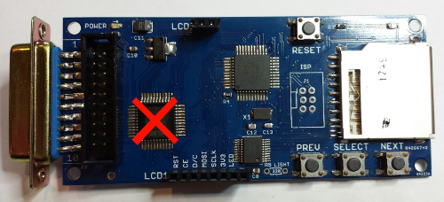
The most common failure I’ve seen is something I call “burnout”, and has affected about 4% of the units. After anywhere from one minute to a few hours of working normally, the Floppy Emu stops functioning, and both the 3.3V regulator and the CPLD become hot to the touch. The AVR, SD card, and LCD still seem to operate normally, but floppy emulation or anything else involving the CPLD no longer work. After some experimentation, I discovered that if the CPLD is removed and replaced using a hot air gun, the Floppy Emu can be returned to normal functioning and the problem does not reappear.
Hot chips imply a short circuit somewhere. Measuring the current draw is tricky, because Floppy Emu is normally connected directly to the Macintosh which powers it, and there’s no place to insert an ammeter inline and measure the current. I finally broke down and built a simple bench test rig, where the Floppy Emu is powered from an external power supply and no Macintosh is involved. This only provides a way to measure the current draw of the whole board, and not individual chips, but it’s better than nothing.
What I found is that a normal board idling on the main menu screen draws about 124 mA. Removing the CPLD with the hot air gun lowers this to 41 mA, implying that the CPLD and the incremental 3.3V regulator current are about 83 mA combined. That’s a bit more than the CPLD datasheet says is typical, but the actual supply current depends on how the CPLD is configured, so it’s within the realm of possibility. The CPLD current likely increases when the device is active and floppy emulation is happening, but I don’t have any way to measure that with the existing bench test rig.
Next, I measured a Floppy Emu in “half burnout” condition. This one actually functioned OK, but after several minutes it would grow pretty hot and stop working. Unlike the other burnout Emus I’ve had, this one would start working again if it were left to cool off for a minute. With my test rig, I measured this board’s idle current draw at 400 mA, more than three times higher than the normal board. Removing the CPLD dropped the current down to 41 mA again, so it seemed clear the trouble was related to the CPLD and not somewhere else.
So what’s going on with this burnout? It looks like something’s causing the CPLD to draw high amounts of current from the 3.3V regulator, resulting in high power dissipation and overheating in both chips. The regulator has an internal safety switch that will protect it from damage, but the CPLD apparently gets toasted. That makes sense, but what causes the high current draw in the first place? Like a good mystery detective, I came up with a few theories, which I think cover all the possibilities:
- The chip was defective. That’s possible, but blaming faulty chips should always be a last resort. In all the electronics projects I’ve ever built, only once have I ever encountered a problem that was conclusively linked to a faulty part.
- The PCB was faulty, and two closely-spaced CPLD traces were shorted together somewhere. The fact that replacing the CPLD fixed the problem seems to rule out this theory.
- A software error in the AVR program or the CPLD config caused two chips to simultaneously drive the same signal to different values. This seems unlikely, as almost all of the signals are unidirectional, and the only bidirectional signals are controlled by a simple mechanism that would be hard to go wrong. A software error should also affect all the hardware, not just a few units, unless it’s some rare timing-based error that only appears in very specific circumstances.
- The chip was damaged during assembly, due to static electricity or high heat. Possible, but I’ve never encountered a damaged AVR, and it’s the exact same package and pin count as the CPLD, and I handle it exactly the same way during assembly. Maybe the CPLD is more sensitive to mishandling somehow? Seems doubtful.
- I accidentally shorted two CPLD pins together with a poor soldering job. I carefully checked all the pins with a 10x magnifier, and couldn’t find any shorts. Still, this seems like the most plausible explanation.
- The “5V tolerant” chip isn’t very tolerant, and continuous 5V inputs eventually lead to damage. The datasheet seems clear this shouldn’t be true. Recommended operating conditions for a high input voltage are between 2.0 and 5.5 volts.
- “Bad” voltages from the Macintosh damage the CPLD, because it’s the only chip that’s directly connected to the Mac. I can’t rule this out, but it seems unlikely. It’s definitely possible for a vintage Mac’s 5V supply to be out of adjustment, but the CPLD is a 3.3V chip and doesn’t use the 5V directly. The Macintosh signal voltages could be out of whack, but I think that would also cause problems for the Mac itself.
- The Floppy Emu circuit design pushes the CPLD beyond its maximum ratings, causing damage. Maybe there’s some significant voltage overshoot or undershoot somewhere that can cause damage, or a big transient that happens at power-on. Possible, but without a specific culprit to investigate it’s hard to say.
Of these, the most likely explanations are the poor soldering job and the chip damage caused by a design that exceeds maximum ratings. Replacing the CPLD with a new one would fix both problems, since it replaces both the soldering job and the chip itself at the same time. To separate these theories, I took the “half burnout” board, removed the CPLD with the hot air gun, then resoldered the same CPLD. It still failed the same way, and drew exactly the same amount of current, demonstrating that the problem lay with the chip itself and not the soldering.
So I’ve got a few damaged CPLDs. Maybe they came defective from the factory (theory 1), maybe I damaged them during assembly (theory 4), or maybe a rare software bug causes damage (theory 3). Maybe an evil Mac is frying them with 12V logic signals (theory 7). But I’m betting on theory 8, and it’s somehow my own fault for a design that zaps the CPLD with occasional voltage overshoots, power-up transients, or other circuit gremlins that lead to failures in a small fraction of the CPLD chips.
Unfortunately there’s not a lot I can do to test this theory with the current hardware. I can only measure the current drawn by the whole board, not a single chip, and I can’t do any measurements while the board is connected to a Mac. Even if I could, an instantaneous surge in current would be met by the CPLD’s decoupling caps more than the power supply, so it might not even show up in any measurements I did. As for checking individual signals for overshoots or weird transients, it’s just not practical. The CPLD is a surface mount chip with tiny 0.5 mm pin spacing, so there’s no way to connect an oscilloscope or other probe. For now, then, there’s probably nothing to do but keep testing, and try to look for patterns in the timing and nature of future failures that might point to a more specific cause.