Quantcast
Channel: Floppy Emu – Big Mess o' Wires
Viewing all 167 articles
Browse latest View live

Floppy Emu, Large and In Charge

$
0
0

After months of procrastination, I finally assembled the Floppy Emu board and began work on the firmware modifications this week. So far, so good! Despite being out of practice with soldering, the assembly went smoothly, and the board checked out fine electrically. The firmware has now been partially converted to the new microcontroller and pin arrangement, and I’m able to read the SD card and write to the LCD screen without problems.

For those who may have missed the earlier progress updates, Floppy Emu is a floppy disk drive emulator for classic Macintosh computers like the Mac Plus. It plugs into the Mac’s DB-19 port, and behaves exactly like an external Sony 3.5″ disk drive would, so no special system software or other modifications are required. Floppy disk images are stored on a standard SD memory card, and a microcontroller (Atmel ATEMGA1284P) and CPLD (Xilinx XC9572XL) are used to read/write the floppy data. The data is converted into the GCR-encoded serial pulse stream that the Mac expects, exactly like the signal from a magnetic read head flying across a track on a real floppy disk.

The Floppy Emu prototype was constructed on a breadboard, using whatever parts were on hand. The prototype demonstrated 100% successful read emulation of an 800K floppy disk, and partially successful write emulation, depending on the type of write operation and the specific SD memory card used. The new Floppy Emu board shown here uses a more powerful microcontroller and different type of CPLD, and combines everything onto a single custom-made circuit board that fits right into the back of the Mac at the external floppy port. Power is provided by the Mac too, so there’s nothing to do but connect it and go.

These photos show how small the Floppy Emu board is: about 1.75 inches wide and 4.5 inches long, including the DB-19 connector. The SD memory card extends an additional 0.5 inch beyond the end of the board. A roll of Scotch tape is also shown as a size reference. The Floppy Emu board is purple, but in most of the photos you’ll also see an LCD display on a red daughterboard. The LCD daughterboard is socketed, and can be connected and disconnected as needed. It’s the same Nokia 5110 LCD board sold by SparkFun and other several other vendors.

Thanks to its small size, the board fits nicely at the rear of the Mac, right between the mouse and the SCSI connector (or mouse and serial port on older Macs without SCSI).

In addition to plugging straight into the external DB-19 floppy port, Floppy Emu can also be connected using a rectangular 20-pin IDC connector. This is the same connector found on the Mac motherboard, so a standard IDC cable can be used to connect Floppy Emu internally instead of at the external floppy connector. A DB-19 to IDC-20 adapter cable can also be used, such as the Apple II cable from IEC shown below. The cable enables Floppy Emu to connect to the external floppy port at the Mac’s rear, but positioned in the front of the Mac where it’s easier to use.

Everything is looking good so far. The next step is to program the CPLD, so communication with the Mac can be performed. The Floppy Emu board has a Xilinx JTAG connector at the upper-right of the LCD daughterboard, but it’s not populated and I’m hoping not to use it. Instead, my plan is save the CPLD configuration file on the SD memory card, and then use the microcontroller to configure the CPLD using a bit-bang JTAG method described in Xilinx app note XAPP058. Once that’s done, the final step will be to use the more powerful microcontroller on this board (as compared with the prototype) to experiment with new write emulation methods, and hopefully achieve 100% success for emulated floppy disk writes as well as reads.


In-System CPLD Programming Using XSVF Files

$
0
0

Floppy Emu has both a microcontroller and a CPLD working in tandem, and both must be programmed in order for the emulator to function. However, I don’t want to require two separate external programmers and the associated port connectors. My plan is to use a standard external ISP programmer for the microcontroller, but have the microcontroller program the CPLD, using the technique described in Xilinx app note XAPP058. The idea is to have the microcontroller act as an XSVF player, loading the CPLD configuration file from the SD memory card, and bit-banging the four JTAG pins on the CPLD to perform the programming.

This week, I finally got around to working on the XSVF player so I could program the CPLD on the Floppy Emu prototype board. The Xilinx player sample code is written in C, and was fairly easy to integrate into the emulator program. Using the functions I’d previously implemented, it was quick work to add an option to load a config file from the card and execute it with the XSVF player.

Predictably, once all the pieces were in place, it didn’t work. I spent a while checking and re-checking all my assumptions, reviewing the code, and writing debug info to the LCD, but made no progress. Finally I used the oscilloscope to peek at the JTAG signals, and discovered that they weren’t wiggling at all. All four JTAG signals were stuck high. I spent a few more hours chasing various theories why that might happen, and double-checked the electrical connectivity, before I gave up to do something else. Immediately after leaving the room, I suddenly realized what the problem was: in order to programmatically control the microcontroller JTAG pins, the JTAGEN fuse must be turned off, to disable hardware JTAG. Once I did that, the signals began wiggling as expected when I ran the XSVF player.

At this point the outgoing TMS, TCK, and TDI signals looked reasonable, but the JTAG communication still didn’t work. The error code from the player indicated that the TDO data returned from the CPLD didn’t match what was expected. Again the scope proved useful, this time by showing that TDO was stuck low, and never changed its value. No wonder the data didn’t match what was expected– it was always zero.

Here’s where I would normally describe how I finally solved the problem and got everything working, except this time I didn’t. At this moment TDO is still stuck low, and CPLD programming or other JTAG communication is not possible. I’ve examined the TMS, TCK, and TDI signals, and they look reasonable, and appear to roughly match the output of the PC-based XSVF player simulator that’s part of the Xilinx sample. So what might be wrong? Some theories, none of them great:

  • The CPLD’s JTAG controller might not be active. But according to the datasheet, “If the device is in the erased state (before any user pattern is programmed), … the JTAG pins are enabled to allow the device to be programmed at any time. All devices are shipped in the erased state from the factory.”
  • The JTAG controller might be in the wrong state to respond to the commands from the XSVF player. However, I looked at the code, and the first thing it does is reset the controller (by setting TMS high and pulsing TCK five times). This should be OK.
  • The communication from the XSVF player might be garbled or broken. Maybe I accidentally swapped two signals, or introduced a bug in the player code? My preliminary scope debugging shows the signals look OK, so I’m skeptical this is the problem.
  • The JTAG clock might be too fast. Initially the player code resulted in a JTAG clock rate around 500 kHz. I tried slowing it to under 1 KHz with no success.
  • The player might not be waiting long enough for CPLD internal operations to complete. There’s a fairly long discussion of this in the sample code, and I’m fairly sure I did it correctly. When I tried slowing down the player even further, it didn’t help.
  • The XSVF file might be bad. I’m using a file I generated with Xilinx iMPACT, which should simply query the device ID, then terminate.
  • There might be an electrical short between TDO and ground. I’m fairly certain this isn’t the case, because before I disabled microcontroller’s JTAGEN fuse, TDO was about 4.5 volts. Now it’s zero. If there were a short to ground, it would have always been zero.
  • The CPLD might be installed backwards or rotated, so the board trace isn’t actually connected to the TDO pin. I double-checked the orientation, and it looks correct.
  • The CPLD might be damaged or defective.

For the moment at least, I’m stumped. I’m out of ideas for other things to try. I’m going to set this aside for a while, and hope that the solution will suddenly occur to me while I’m working on something else. Or failing that, I may at least come up with new theories that can be tested. Debugging electronics sure can be a pain!

Finally!

$
0
0

The new Floppy Emu prototype is up and running at last! Today I was able to boot a Mac Plus from the new emulator board for the first time. It’s still rough around the edges, but it works. Copy a Macintosh disk image to your SD memory card, then plug the Floppy Emu board into your Mac’s external floppy port, and presto: instant disk drive. Your vintage Mac never even knows it’s not the real thing, so everything runs just like it would with a real external floppy drive.

It’s hard to believe it was nearly five months ago that I set out to replace my first ball-of-wires breadboard prototype with something better. The changes seemed simple enough: switch to a more powerful microcontroller from the same family, substitute a different brand of CPLD, add a few more buttons and connectors, and mount the whole thing on a small circuit board. But then I let the project gather dust for a few months, and when I returned to it, almost everything that could possibly go wrong did. Seemingly minor changes to clock speeds and interrupt configurations led to all kinds of head-scratching failures. They’re not interesting enough to detail, but you can imagine a string of long evenings filled with me pounding my fist on the desk and shouting rude things at the monitor.

One of the coolest features of the new board is that the microcontroller can program the CPLD via JTAG, using the XSVF player code that I discussed in my previous post. Copy a firmware.xvf file to the SD card, reset the Floppy Emu board while holding down both PREV and NEXT, and the CPLD will be updated with new firmware in about 20 seconds. That means an external Xilinx programmer isn’t needed at all, which is a huge win. I hope to later implement bootloading of the microcontroller from the SD card too. If I ever reach the point of selling assembled units, that means end users could update both the CPLD and the MCU just by copying the necessary files to the SD card, without any programming hardware at all.

There’s still a lot left to do. I haven’t yet tested write emulation with the new prototype, so that’s the first task. It should work, but it took me so long to get read emulation working that I wanted to savor the success for a while before enabling and testing the write emulation code. Then I’ll look at some new buffering schemes for write emulation, using the extra RAM found in the ATMEGA1284P microcontroller that the new prototype uses. That should hopefully make write emulation more reliable than in the first prototype. At some point, I also need to add support for 400K and 1.4MB floppies, since the current emulator is 800K only.

The user interface needs improvement too. I’d like to add a nicer way to trigger CPLD programming, and a menu to select from among many disk images on the SD card. It would also be nice to add features like an auto-insert option, to insert a particular floppy image into the virtual drive immediately when Floppy Emu is first powered on.

Two features that you probably won’t see are emulation of more than one floppy drive at a time, and emulation of disks larger than 800K (or 1.4MB on those machines that support it). Those limitations come from the Macintosh floppy driver code in ROM, so to change them I’d need to write a new driver, and find a way to load it using the built-in driver so that the new driver replaces the built-in driver after loading. In fact, I’d probably need to write a new driver for every Macintosh model, since they don’t all access the floppy hardware the same way. It’s all theoretically possible, but would be a major software project that I’d prefer to leave to someone else to attempt.

To my friend Tom who keeps hounding me asking when Floppy Emu will be ready, here you go. Your Mac 512K can now live again!


Build Your Own Floppy Emu

$
0
0

Over the past several months, many people have written to me about the Macintosh Floppy Emu, asking if they could buy one, or when the project would be finished. Since I haven’t made any progress on Floppy Emu in ages, I’m doing the next best thing and releasing the design files and build instructions to the community. If you’re skilled with a soldering iron and embedded development tools, you can use these to build your own Floppy Emu, or improve upon its design.

Warning! Building a Floppy Emu requires advanced soldering skills. Almost all the parts are surface mounted, and there are several SMD chips with fine-pitch 0.5 mm pin spacing. These can be soldered by hand, but it’s tedious, error-prone work. If you’ve never done this type of soldering before, think hard before starting this project. Now with that out of the way, let’s get started!

Download the Floppy Emu design file archive

What You’ll Need

  • A Windows PC
  • AVR Studio 5 software from Atmel. This is free software. AVR Studio 6 probably works too, but I haven’t tried it. AVRDUDE should work as well.
  • An AVR programmer, such as the AVRISP mkII
  • A high-speed class 10 SD or SDHC card
  • Soldering iron
  • Patience

Making a PCB

To begin building your Floppy Emu, you’ll need a printed circuit board. There are many on-line services that will make these for you, using a set of layout files called Gerbers. You will find the Floppy Emu Gerbers in the file archive, in the directory eagle\floppyemu\gerbers.zip. I recommend using the Dorkbot PDX PCB Order service to get the PCB manufactured. Send them the Gerber files, and they’ll make three copies of the PCB for about $30, with a turn-around time of a few weeks. The guy who runs the PCB service is very helpful if you have questions.

Getting the Parts

While you’re waiting for the PCB to be manufactured, you can locate all the other parts you’ll need to assemble the Floppy Emu. You’ll find a complete parts list in the file archive. The total parts cost should be about $40, which is dominated by the AVR microcontroller and the Xilinx CPLD.

One of the required parts is a male DB-19 connector, which mates with the Mac’s external floppy port. These can be very difficult to find, and IEC is the only supplier I know that has them. If you can’t find a DB-19 solder type connector, you can still use the Floppy Emu with its alternate IDC20 connector, which is readily available from electronics suppliers. With the IDC20, there are several different connection options:

  • Connect the IDC20 to the internal floppy connector inside your Mac (you will need an IDC20 cable)
  • Connect the IDC20 to the circuitry inside a real external Apple floppy drive enclosure, after removing the drive guts
  • Use an Apple II DB-19 to IDC20 cable

If you don’t already have them, you’ll also need a high speed class 10 SD or SDHC card, and an AVR programmer like the AVRISP mkII.

Assembly

Here’s where things get fun! Refer to the file floppy-emu-layout.png for placement information, or check the schematics.

The first step is to solder and test the AVR.

  1. Solder the AVR. Pay attention to the orientation – the dot in the corner of the chip should match the dot on the silkscreen. I recommend using the drag solder technique. Begin by soldering two pins on opposite corners of the chip to tack it in place. Verify that the pins are perfectly aligned with the pads on the board before proceeding. Now goob an absurd amount of solder onto the remaining pins. You will probably bridge most of the pins together – that’s OK. Finally, go back with a solder wick and flux, and wick away all the excess solder. Surface tension will hold the solder onto the pins and pads where it belongs, while the excess is magically wicked away. Use a 10x jeweler’s loupe to visually inspect the pins for tiny bridges or gaps.
  2. Solder the crystal, the 18pF capacitors C12-C13, the AVR decoupling capacitors C4-C7 (these are on the back of the board), the voltage regulator, and the regulator capacitors C10-C11. Also solder the DB-19 connector. It fits along the edge of the board, with the thickness of the board fitting between the two rows of solder cups.

The AVR microcontroller should now be functional. You can use AVR Studio to test it out.

  1. Install the AVR Studio 5 software on your PC and run it.
  2. Connect the Floppy Emu board to your Mac, and turn on the Mac.
  3. Connect the AVRISP mkII programmer to your PC.
  4. Press the ISP connector into the board, but do not solder it yet. If it is soldered too soon, it will be in the way of your iron later.
  5. Connect the AVRISP’s programming cable to the ISP connector on the board.
  6. Click on the AVR Programming button in the toolbar. It looks like a chip with a lightning bolt.
  7. In the programming dialog, set Tool to AVRISP mkII, Device to ATmega1284P, and Interface to ISP
  8. Click the Apply button
  9. Where it says Device ID at the top, click the Read button. Push the ISP connector firmly sideways while you do this, to ensure its pins make electrical contact with the board.

If everything is working, the Device ID field should now display 0x1E 0×97 0×05. If it does not, or you encounter an error, review the steps above, then go back and carefully re-check all the solder connections. Do not proceed further until you are able to retrieve the AVR device ID.

The next step is to program the AVR with the Floppy Emu software.

  1. Open the AVR Programming dialog again.
  2. From the list at the left, click Fuses to display fuse information.
  3. Set the fuses:
    • BODLEVEL – disabled
    • OCDEN – off
    • JTAGEN – off
    • SPIEN – on
    • WDTON – off
    • EESAVE – off
    • BOOTSZ – 4096W_F000
    • BOOTRST – off
    • CKDIV8 – off
    • CKOUT – on
    • SUT_CKSEL – EXTXOSC_8MHz_XX_16KCK_65MS
  4. Click the Program button in the fuse panel. Push against the ISP connector with your finger while you do this.
  5. From the list at the left, click on Memories to display AVR memory information
  6. Under Flash, verify that “Erase device before programming” is checked
  7. For the Flash filename, choose AVR\release\floppyemu.hex from the file archive
  8. Under Flash, click the Program button. Push against the ISP connector with your finger while you do this.
  9. Remove the ISP connector from the board.

Congratulations, the AVR setup is now complete! The next step is the Nokia LCD.

  1. Solder the level converter (the 74LVC244), its decoupling capacitor C8, and the 10K resistor R4.
  2. Solder the two 8-pin male 0.1 inch headers to the Nokia LCD.
  3. Solder the top 8-pin female 0.1 inch header to the board. Place the bottom header in the board, but do not solder it yet.
  4. Connect the LCD to the Floppy Emu board. The thicker part of the LCD bezel should be at the top.

The LCD should now be functional. Connect the Floppy Emu to your Mac, and turn the Mac on. If everything is working, the LCD should show “SD Card init error”.

The SD card reader is next.

  1. Solder the SD connector, and its decoupling capacitor C9.
  2. Insert the SD card into your PC.
  3. Format the SD card as a FAT32 disk.
  4. Copy all the files from the SD files directory in the file archive onto the SD card. Don’t copy the directory itself, only the files that are in it.
  5. Put the SD card into the Floppy Emu.

Connect the Floppy Emu to you Mac, and turn the Mac on. If everything is working, the LCD should show “no disk 79/0″.

The final assembly step is the CPLD.

  1. Solder the CPLD. Pay attention to the orientation – the dot in the corner of the chip should match the dot on the silkscreen. Use the same technique for soldering the CPLD that you used for the AVR.
  2. Solder the CPLD’s decoupling capacitors, C1-C3. These are on the back of the board.
  3. Solder the LEDs and their resistors, R1-R3. The silkscreen shows the proper orientation for the LEDs.
  4. Solder the four tactile switches.
  5. Solder the remaining connectors into place.

Now it’s time to program the CPLD. The unfilled JTAG header footprint on the board could be used to program it directly with a Xilinx programmer, but it’s not used by this version of Floppy Emu. Instead, the AVR programs the CPLD indirectly, using a firmware file stored on the SD card.

  1. Ensure the file firmware.xvf is on the SD card. This is part of the SD files collection that you should have copied to the card earlier.
  2. Put the SD card into the Floppy Emu.
  3. While your Mac is turned off, connect the Floppy Emu to the Mac.
  4. Hold down both the PREV and NEXT buttons, then turn on the Mac.
  5. Follow the instructions on the LCD to load the firmware file to the CPLD.

That’s it! Turn the Mac off, then on once more, and you’re done.

Using the Floppy Emu

When it’s turned on, the Floppy Emu scans the root of the SD card for files with a .dsk extension, and shows a menu of available disk images. It begins with the disk “out of the drive”. Use the PREV/NEXT buttons to select a disk image file, then press the SELECT button to insert it. After the disk is inserted, the LCD display shows the current track number and side of the emulated disk drive head.

You can use other floppy image files in addition to the ones included in the archive – just copy them onto the SD card. The Floppy Emu expects raw 400K or 800K disk images without any headers or other information, so a disk image file should be exactly 409,600 or 819,200 bytes. If you have some 400K or 800K disk images that you’ve been using with Mini vMac or another Macintosh emulator, they should work with Floppy Emu as well. Only 400K and 800K disk image files are supported – 1.4MB images will not work.

With a high-speed class 10 SD card, all your standard read and write operations to the floppy will work, just as if it were a real external floppy disk. You can boot the computer, save documents from MacPaint, or copy files in the Finder. Read operations will also work OK with a slower SD card, but write operations may fail.

Formatting or initializing the floppy in the Finder is not supported on any type of SD card, and will fail. If you need a blank disk image file, create one using a Macintosh emulator program and then copy it to the SD card. Certain kinds of bulk transfer write operations are also unsupported, such as using a disk copy program to copy data to the floppy.

Extending Floppy Emu

The C source code for the microcontroller program is provided in the file archive. You can build it with AVR Studio, generate a new floppyemu.hex file, and load it to the microcontroller using the AVRISP mkII.

For the ambitious, the ATMEGA1284P microcontroller that’s used here has much more RAM than is needed by the current program. It could be used to implement some kind of sector buffering scheme, which could enable slower SD cards to support writes reliably, and all cards to support formatting and disk copying.

The Verilog source code for the CPLD is also provided. You’ll need Xilinx’s free ISE WebPACK to build it. Export an XSVF file, and rename it to firmware.xvf. Then copy the file to the SD card, and load it onto the CPLD as you did before. I’m not sure why you’d need to change the CPLD design, but maybe you’ll find a reason.

The CadSoft EAGLE schematics and board files are included in the file archive too, for anyone who wants to experiment with changing the hardware design. You can use the freeware version of EAGLE.

Happy hacking!

Floppy Emu Disk Menu

$
0
0

I finally got around to building a proper floppy disk image selection menu. Instead of loading a hard-coded rfloppy.dsk disk image file from the SD card, Floppy Emu now scans the SD card for all files with a .dsk extension, and displays a menu of available disk image files. The PREV/NEXT buttons navigate the menu, and the SELECT button inserts the selected disk image into the virtual floppy drive.

When a disk image is inserted, the LCD displays the name of the Macintosh volume that’s inside the disk image – “System Tools” in the example above. It also shows the current track and side being accessed. For write operations, the LCD displays the track, side, and sector that was written, as well as the time required for the write.

Download the Floppy Emu file archive for the new firmware.


400K Floppy Support

$
0
0

I’ve added 400K floppy support to Floppy Emu, so now you can boot up System 1.1. The fix took all of fives minutes, so why didn’t I do this ages ago? Grab the latest Floppy Emu file archive for the new software.

Floppy Emu Disk Emulator For Vintage Macs – Now For Sale

$
0
0

If you’ve ever wanted a Floppy Emu, but lacked the time or soldering skills to build one yourself, you’re in luck! I’ve put two Floppy Emus up for sale on eBay. These were hand-built using the leftover parts from my original prototype, and when they’re gone, they’re gone!

Want one? You can find the eBay listings here: Auction 1Auction 2

Note: Floppy Emu has been updated. This video and text describe an earlier version.

Floppy Emu is a prototype floppy disk drive emulator for classic Macintosh computers, using an SD memory card and custom hardware to mimic a 400K or 800K 3.5 inch disk drive and floppy disk. It plugs into the Mac’s external or internal floppy connector, and behaves exactly like a real disk drive, requiring no special software on the Mac. Disk image files are stored on the SD card from a PC, and then read and written by Floppy Emu during the normal operation of the Macintosh, with each image file appearing to the Mac as a different floppy disk. You can boot from the emulated floppy, or boot from another drive and use the emulated floppy as a second disk.

What You Will Need

  • A high-speed class 10 SD or SDHC card
  • A PC or Mac capable of writing files to the SD card
  • A collection of Mac disk image files in .dsk format

Optional

  • An extension cable so Floppy Emu can be moved to a convenient location, such as this one

Compatibility

This is experimental hardware, so expect some bugs. Floppy Emu is designed for classic Macs that support a 400K or 800K internal or external floppy drive. It does not emulate the 1.4MB Superdrive, nor can it use 1.4MB disk images. I’ve successfully tested Floppy Emu with a Mac Plus and a Mac 512Ke. Another person has confirmed it also works with the Mac SE. I’ve had one report that it does not work with the Mac 128K or Mac II. Compatibility with other systems is untested. The full source code and hardware specs are available here on the BMOW site, so if you’re a programmer, you can help improve the software and extend compatibility to more Mac models.

FAQ

  • Can I boot from an emulated floppy? Yes you can!
  • Does this require a special driver or INIT on the Mac? No, nothing special is required.
  • What size disk image files are supported? 400K or 800K disk images in .dsk format.
  • What if I don’t have a high-speed class 10 SD card? Reading will work fine, but writing may fail.
  • Can I format the emulated floppy, or use it as a destination for disk copy programs? No. Floppy Emu only supports “normal” sector-by-sector writing, such as copying files in the Finder, or saving data from within a program.
  • Can I emulate multiple floppies at once? Floppy Emu can store as many disk image files as your SD card will hold, but only one can be “inserted” in the drive at any given time.
  • Can I save Mac files to the emulated floppy, then put the SD card in my PC to read them back? Yes. Your files will be inside the .dsk disk image. A software-based Mac emulator or Mac disk image tool can extract individual files from the image.


Fixing 30 Year Old Apple ROM Bugs

$
0
0

After nearly a year of inactivity, I’ve started work on Floppy Emu again! One of my first priorities was compatibility with Macs that have a 400K floppy drive – the original Mac 128K, and the Mac 512K (not the 512Ke). Floppy Emu emulates a 400K/800K external floppy drive, and it works fine with 400K disk images, so I originally assumed it would have no problems on those old 400K-based machines. Wrong! Reports trickled in of mysterious Sad Mac errors and other problems when using Floppy Emu with those oldest Mac models. After ignoring the problem for months, I finally got ahold of a Mac 512K so I could investigate things firsthand.

Some brief experimentation showed that Floppy Emu was at least partly working with the 512K. When I “inserted” a disk image of a non-bootable disk, the Mac rejected it and showed the X’d disk icon. But when I inserted a bootable 400K system disk image, the Mac chewed away for a moment, then died with a Sad Mac error code 0F0004. So it was clear the Mac 512K could recognize the difference between a bootable and a non-bootable disk, but was failing to actually boot when using Floppy Emu. The same disk image and Emu hardware booted fine on a Mac plus, so the problem looked like an unknown incompatibility between the Mac 512K and Floppy Emu.

The Sad Mac – such a cute way for a computer to die. Much friendlier than a blue screen of death, but just as fatal.

From past experience, I knew the Mac 128K and 512K used a different version of the Apple ROM than found in the 512Ke and Mac Plus. The 512Ke/Plus ROM added support for 800K floppy drives. But as long as only 400K disk images are used, I couldn’t see any reason Floppy Emu shouldn’t work on 128K/512K Macs with the old ROMs. After all, how would the Mac even know that Floppy Emu wasn’t a 400K drive? The real 400K and 800K drives are virtually identical, with the same connector, same internal registers, etc. The only difference is that one is a single-sided drive and one is double-sided. Also the Mac directly controls the speed of a 400K drive with a PWM signal, but an 800K drive ignores the PWM signal and self-regulates its speed.

I hunted the internet for details on 30-year-old boot errors, and found two explanations for error 0F0004. One said “Voltage too Low, adjust voltage to +5.0v.” and another said “Division by Zero”. How could there be two such radically different meanings for the same error? But things started to fall in place after I found this Apple Tech Note, which said that 0F0004 was a result of using an 800K external disk drive on the Mac 128K/512K with the old ROMs. So somehow the Mac was still identifying Floppy Emu as an 800K disk drive, which caused it to die. But how did it know?


ROM Diving

When all else fails, it’s time to look at the source code. In this case that meant disassembling the ROM from the 128K/512K to find out what the floppy driver is doing. I’ve done this a few times before now, but it’s still a major pain. Even with a 68K disassembly tool, and substituting symbolic names for all the Mac memory-mapped hardware, it’s still an opaque mess of assembly language code that doesn’t yield its secrets easily. It’s hard enough just to locate the relevant floppy routines, let alone understand the fine details of how they work. But after a day of poking and prodding, I found some code that looked very suspicious:

P_Sony_MakeSpdTbl:
1E82   285F                  Move.L    (A7)+, A4
1E84   343C 0080             Move      $80, D2		; set PWM value to $80
1E88   615C                  Bsr       P50		; measure TACH speed, get speed1 result in D4
1E8A   6B56                  BMI       L309
1E8C   2604                  Move.L    D4, D3		; copy result to D3
1E8E   343C 0100             Move      $100, D2		; set PWM value to $100
1E92   6152                  Bsr       P50		; measure TACH speed, get speed2 result in D4
1E94   6B4C                  BMI       L309
1E96   2A04                  Move.L    D4, D5		; copy result to D5
1E98   9A83                  Sub.L     D3, D5		; D5 = difference between speed1 and speed2
1E9A   E38B                  LsL.L     $1, D3
1E9C   7C04                  MoveQ.L   $4, D6
1E9E   4BFA FFC8             Lea.L     DT19, A5
1EA2   6100 FCA2             Bsr       Sony_SetupSonyVars
1EA6   47F1 101A             Lea.L     $1A(A1,D1.W), A3
1EAA   7400       L304:      MoveQ.L   $0, D2
1EAC   341D                  Move      (A5)+, D2
1EAE   2E02                  Move.L    D2, D7
1EB0   D45D                  Add       (A5)+, D2
1EB2   E24A                  LsR       $1, D2
1EB4   D484       L305:      Add.L     D4, D2
1EB6   9483                  Sub.L     D3, D2
1EB8   6A02                  BPL       L306
1EBA   7400                  MoveQ.L   $0, D2
1EBC   EF8A       L306:      LsL.L     $7, D2
1EBE   6702                  BEQ       L307
1EC0   84C5                  DivU      D5, D2		; divide D2 by (speed2 - speed1)

Comments were written by me, after analyzing the code. This particular routine does some kind of calibration of the floppy drive – it varies the PWM signal, then measures the resulting drive speed as indicated by a value called TACH. I think it’s trying to establish a linear relationship between PWM and TACH, since that relationship may vary slightly between real 400K drives. There’s a lot going on in this routine, and I’ve truncated it to only show the first 25 instructions. But notice it contains a DivU instruction? There aren’t many places that division is used in the original Mac ROM, so that’s significant.

Looking deeper, the routine makes two drive speed measurements, then does some math to compute a value in D2, then finally divides D2 by the difference between the two speed measurements. But what happens if the two speed measurements were equal? Division by zero! Hello, 30 year old ROM bug.

On a 400K drive that’s controlled by the Mac’s PWM signal, the speed measurements will always have different results, because the PWM is different during each measurement. But on an 800K drive which self-regulates its speed, and on Floppy Emu which has a totally fake speed, the PWM changes will have no effect. That means both speed measurements will get the same result, and the Mac will crash with a division by zero error when it calls this ROM routine. Getting two different speed measurements was probably a safe assumption in 1983/1984 when the code was written, but it still would have been nice to do some defensive programming and add a zero check there, to handle the case of a broken drive or broken assumptions.


Fixing It

Once I understood the cause of the 0F0004 error, the question was how to modify Floppy Emu to avoid it. The TACH speed signal that Floppy Emu generates is obviously fake, since there are no moving parts. It calculates how fast the drive motor should be spinning, given which track is being accessed, and creates a series of pulses on TACH at the appropriate rate. To avoid the division by zero crash, the TACH rate needs to vary, so that two successive measurements see different TACH speeds.

One solution would be to use the PWM signal from the Mac, since that’s its purpose. By analyzing the PWM duty cycle, the Floppy Emu hardware could infer how fast the Mac wanted the drive to spin, and generate an appropriate TACH to match. Unfortunately, the hardware doesn’t even have the PWM pin connected. And if it did, it’s not certain that it could do the necessary duty cycle and TACH calculations fast enough, or efficiently enough to fit in the remaining logic space.

My solution was to constantly flutter the drive speed TACH signal. The flutter rate must be fast enough that two successive measurements will see different rates, but not so fast that two successive measurements will span the entire flutter cycle and so see the same rate. The flutter amplitude must be large enough for the speed measurements to be different, but not so large that the measured speed falls outside the valid range for the current track being accessed. With a little experimenting, I settled on a flutter cycle period of 640 ms and a flutter amplitude of about 0.25%.

And it works! The image above shows the Mac 512K running System 0.97, Finder 1.0, booted from Floppy Emu. Those fonts sure are weird.


A Bit of History

When Macintosh external 800K floppy drives first became available, in 1985/1986, owners of the Mac 128K and 512K faced the same problem I did here, only they couldn’t modify the drive’s TACH behavior to work around the ROM bug. Instead, Apple released a system patch called HD20 which fixed the bug and added 800K drive support. But using it was a pain: you had to boot from a 400K floppy in the internal drive first, which contained the HD20 patch, and then you could mount an 800K floppy in the external drive. Booting from an 800K drive wasn’t possible. It wasn’t a very nice solution.

If that ROM routine’s author had added a zero check, this wouldn’t have been necessary. Mac 128K/512K owners could have booted directly from an 800K floppy in the external drive, loading the HD20 init in the process. Everything would have been great. Instead, that divide by zero bug doomed them all to a miserable 800K experience.

When Apple and Sony were developing the 800K external drive, they must have known this was a problem, and they could have used the solution I did to flutter the TACH speed. In 1985 they couldn’t just drop a 25-cent microcontroller into the drive to synthesize TACH, but they could have added a simple RC circuit to inject some AC “noise” into the TACH signal at the appropriate amplitude and period, achieving the same result. Everything would have been great. But they didn’t, and all those 128K/512K owners were forced to endure the 400K floppy boot-swap dance forever.


1.4 MB High Density Floppy Emulation

$
0
0

WOOOOO! Floppy Emu’s last big goal has been reached, and 1.4 MB disk emulation is now working! The photo shows a Mac Classic, booted into System 7.0 from a 1.4 MB high-density disk image. Combined with other recent improvements, this means Floppy Emu now works for 400K, 800K, or 1440K disk images in raw .dsk or DiskCopy 4.2 .image format, on any Mac from the 128K to the Mac II series and beyond.

1.4 MB disk support proved to be very similar to 400K/800K support in concept, but completely different in details. Data on 400K/800K disks is stored using a technique called GCR, which dates all the way back to the Apple II. GCR defines how data is encoded as flux transitions on a magnetic disk (or an emulated version of one, like we have here). In contrast, 1.4 MB disks store data using a technique called MFM, which is used by PCs as well as other classic systems including the Amiga and Atari ST. While GCR and MFM serve the same purpose, they are quite different, so Floppy Emu’s microcontroller and CPLD software both had to be extensively modified to add MFM support. For the curious, this Atari ST page has an outstanding explanation of floppy data encoding and MFM, almost all of which is relevant to the Macintosh too.

Aside from the MFM encoding change, another big challenge was maintaining MFM’s higher data rate. A Macintosh 400K or 800K floppy sends bits to the floppy controller at 500 kHz, but a 1.4 MB floppy sends bits at 1 MHz! That means Floppy Emu’s AVR microcontroller and companion CPLD needed to work twice as fast as before to serve data to the Mac, or else an underrun error would occur. My first attempts resulted in something that was almost but not quite fast enough, leading to a maddening situation where data transfers seemed to work much of the time, but would flake out with seemingly random errors before an entire sector could be transferred. In the end I had to review the C compiler’s assembly output, and do some cycle counting by hand, in order to optimize the code to the point where it was fast enough to consistently meet the data rate demands.

Beyond the MFM differences, high density Mac disks also use a different signature than 800K disks for tagging sector address and data blocks, and use a different checksum algorithm. 800K disks use a near-incomprehsible checksumming algorithm that was probably invented by Woz himself, while HD disks use a standard CCITT-CRC16 algorithm. Then just for laughs, high density disks also use a 1-based numbering scheme for sectors, instead of 0-based. That little twist took me quite a while to recognize!

The last hurdle was related to the larger size of a high-density floppy track, and I still don’t have a perfect solution for it. For 800K disks, the number of combined sectors on both sides of a track is variable, but is never more than 24. With 512 byte sectors that’s 12K of data – small enough to fit into the microcontroller’s 16K of RAM with some room to spare. But for high-density disks, there are 36 sectors and 18K of data – it won’t fit! Instead of buffering an entire track in RAM, then, I had to fall back to the technique I originally used for 800K disks, and do SD card transfers on the fly at the instant the data is needed. It works well enough when reading the disk image, but when writing it’s very sensitive to the speed and variability of the SD card transfers.

There are still many little bugs to fix and things to polish, and a few other features I’d like to add, but with the addition of 1.4 MB support I think Floppy Emu is effectively finished. Or if not finished, at least worthy of a “1.0″ version number release. My next plans are to polish up the code and documentation, squash a few more bugs, and then build some Floppy Emu units for those who want one. Happy hacking!


Getting Ready to Sell

$
0
0

I’m almost ready to start selling Floppy Emu hardware! My plan is to offer two options: a fully assembled and tested unit, and a “DIY kit” containing the PCB board, LCD, and DB-19 connector. These are the hardest parts to find, and the ones where shipping costs kill you if buying individual quantities, so the DIY kit should be helpful for people making their own builds. The assembled units will be hand-built and tested by me, and I’m a little scared about signing myself up for that much labor. If there’s enough demand I’ll look into having an electronics assembly shop do the work, but I expect large quantities are necessary for that to be economical. I haven’t decided on prices yet, but it’ll be low enough that people find it a good value, while still high enough to make it worth my time and effort.

Meanwhile, feature development continues. I’ve completed a revision 1.1 board, which has a number of small changes:

  • LCD backlight
  • mounting holes (can build a case for the board)
  • support for the lock tab on the SD card
  • removed the motor LED, since motor status is now displayed on the LCD
  • removed the unused JTAG connector footprint
  • repositioned the buttons and status LED
  • added a test point for oscilloscope probing
  • probably some other things I forgot

I also added support for Disk Copy 4.2 disk images, long filename support, and subdirectories on the SD card (see photo). Things were getting a little out of hand once there were more than a few dozen disk images on the SD card, and the subdirectories really help. This makes OS installs almost enjoyable! Just download the disk images from Apple, copy them to your SD card, boot the Mac from the Install Disk 1 image, and off you go.

The last major piece of the puzzle is 1.4 MB write support. I’ve got this partly working already, and writes of individual sectors and small files are OK, but writing a larger file to a 1.4 MB emulated floppy causes things to go haywire. The lack of any real debugging tools (other than printing to the screen) makes this a pain to troubleshoot, but I think I’m pretty close to resolving it.

New Floppy Emu Boards and Supply Noise

$
0
0

I finally got the new Floppy Emu revision 1.1 boards!  Rev 1.1 has a few minor tweaks to prepare for selling assembled hardware. I built four of them with a soldering mini-marathon, and three of them work. The fourth I think I toasted somehow, but I’ll check it in more detail later. 75% yield isn’t so good. :-)

Unfortunately something isn’t quite right. With the new boards I’ve built so far, I’m seeing anywhere from 3X to 10X more noise on the 5V and 3.3V supply lines, and I think this is causing random resets and spurious interrupts and other phantom problems. The noise is very regular, with a frequency of between 80 kHz and 130 kHz on both supplies.  I was able to bring the supply noise under control by soldering an extra 10uF capacitor between the 3.3V and GND pins on the LCD, but it shouldn’t need one, since there’s already a 10uF cap between 3.3V and GND on the main board. Yet the difference with and without the extra cap is like night and day:

Rev 1.1:
new LCD (with extra 10 uF cap) and SD card: 80 mV noise on 5V supply, 100 mV on 3.3V supply
new LCD and no SD: 60 mV on 5V, 50 mV 3.3V
old LCD and SD card #1: 380 mv on 5V, 100 mV on 3.3V
old LCD and SD card #2: 840 mv on 5V, 280 mV on 3.3V
old LCD and no SD: 900 mv on 5V, 340 mV on 3.3V

Rev 1.0:
new LCD and SD card: 100 mV on 5V, 120 mV 3.3V
new LCD and no SD: 80 mV on 5V, 120 mV 3.3V,
old LCD and SD card: 100 mV on 5V, 120 mV 3.3V
old LCD and no SD: 80 mV on 5V, 100 mV 3.3V

I guess I could just go with the extra capacitor on all new boards, and call it done, but I’d really like to understand what’s going on. Quite a few things changed between revisions, any of which could affect supply noise:

  • New board design relocated some parts and re-routed some traces
  • Boards were manufactured by a different fab
  • Using an ATMEGA1284 instead of ATMEGA1284P
  • Different brand of 3.3V regulator

I’m tempted to blame the 3.3V regulator, but I don’t quite see how it could be at fault. The old regulator from rev1.0 and the new regulator from rev1.1 are virtually identical.

I’m going to do some more experiments before deciding how to proceed. If you’ve got any ideas on what to check, please leave a note in the comments!


Manufacturing is Hard

$
0
0

There’s a big difference between building one of something, and making a repeatable process to build 10 of them, or 100. Unfortunately I’m learning that the hard way while I try to get some more Floppy Emu boards ready to sell. If I had any hair, I’d be pulling it out! I never thought this would be so hard.

If you haven’t been following the earlier posts, Floppy Emu is a floppy disk drive emulator for vintage Macintosh computers. I built the first Floppy Emu for my personal use about a year ago, and while the soldering was a little challenging, everything worked once it was done. I posted the design on the BMOW web site, and since then I’d estimate about 10 other people have built their own Floppy Emu boards. Then in October I built two more boards from my remaining parts stock, and sold them on eBay. I tested those thoroughly before I sold them, so I’m confident those boards were working well.

The eBay sale generated lots of interest and requests for more boards, so in late October I created board revision 1.1 in preparation for a small hand-made “production run”. The board layout changed slightly to make room for mounting holes, and some board traces were moved or added. I switched to a different PCB supplier, changed to a different brand of 3.3V LDO regulator, and substituted the Atmega1284 for the Atmega1284P to save a few pennies.

I built four of the rev 1.1 boards, and initially none of them worked. As described in my previous post, the new brand of 3.3V regulator proved to be unstable when combined with the output capacitor I’d been using. The oscillations on the 3.3V and 5V supply lines caused all kinds of crazy behavior and malfunctions that drove me crazy. I’ve since found that replacing the 10 uF ceramic output capacitor with a 33 uF tantalum solves that particular problem. Yet even with the capacitor fix, one of the boards exhibited occasional random write errors, and I somehow toasted another one during assembly.

Later I discovered a flaw in my CPLD firmware that was shorting the Mac’s PWM drive speed control input to GND. Floppy Emu doesn’t actually use that input, but shorting it to ground is not very nice, and may have damaged the CPLD, the Mac, or both. This only affected the rev 1.1 boards. That firmware flaw is now fixed, hopefully without any permanent damage.

I’ve since built two more of the rev 1.1 boards. One worked fine, but the other showed the same pattern of occasional random write errors. Of the six rev 1.1 boards I’ve built, that means I only have three working boards. Arghh! 50% yield is not good. The random write error is maddening. It doesn’t happen very often, so it’s necessary to do a LOT of testing before I can be confident a particular board does or doesn’t  have this problem. I spent a long time with a lens, an oscilloscope, and a debugger trying to explain what’s going wrong, but failed. My best theories are:


Software Bug – Perhaps there’s a problem with the Floppy Emu software, like a timing bug or uninitialized variable, and tiny variations in boards or components cause the bug to appear or disappear. This was my first guess, but if true I would expect a continuous distribution of bugginess across boards, rather than two groups of “working” and “not working” boards. I tested the working boards heavily, and they really do work 100%. I also made many experimental software changes that I thought might cause the problem to appear or disappear, but there was no change in behavior. And to my knowledge none of the rev 1.0 boards have this problem, even though they use the same software.

Soldering Mistake – I may have created a bad solder joint somewhere, leading to flaky behavior. That’s possible, but it seems pretty unlikely I’d make the exact same soldering mistake twice in six boards. And I’ve visually inspected the problem boards carefully with a 10x magnifier, and touched up all the likely problem points with an iron, without any success.

CPLD Damage – Some of the CPLDs might have been damaged by the firmware bug that shorted PWM to GND, resulting in buggy behavior even after the firmware was fixed. That’s certainly possible, but then why weren’t all the CPLDs damaged? Why just two of them? If this is the true explanation, then future rev 1.1 boards should all work OK now that the firmware bug is fixed.

Atmega1284 vs Atmega1284P Variation – Maybe some minor difference between the two types of the AVR microcontroller is causing unexpected problems. As far as I know, the only difference is that the “P” version uses Atmel’s Pico-Power system to enable very low power sleep modes. Since I’m not using those sleep modes, that difference shouldn’t matter.

Board Design Flaw – The rev 1.1 board could contain a design mistake not present in the original board, like substantial coupling between neighboring traces, signal reflections, or other noise that leads to intermittent problems. While the layout changes between rev 1.0 and 1.1 were minor, I can’t rule this possibility out.

Manufacturing Flaw – The rev 1.1 boards from Smart Prototyping might not be built to the same tolerances as the original boards from Dorkbot PDX. In terms of published specs like minimum trace width and spacing, the Smart Prototyping process should be fine, and I used their design rules file to verify my board in Eagle. I know other people have been successful with rev 1.0 boards not made by Dorkbot PDX, though I don’t think any have used Smart Prototyping specifically.


Unfortunately I’m at one of those points where I really don’t know where to go next. I could build a few more boards to test the CPLD damage theory. Or get some more Atmega1284P’s and build a few boards with those, or experiment with going back to the original PCB manufacturer or the rev 1.0 board design. But each of those experiments would require more time and money to test the theory. I’d need to see at least five good boards and zero bad ones before I had any confidence that I’d solved the problem. Spread across all the possible problem causes, I could end up building several dozen test boards, and still come up empty-handed if the true cause is a software bug or something else I haven’t considered.

Floppy Emu – Ready For Sale

$
0
0

The Floppy Emu Macintosh Disk Emulator is finally available for sale! Get one now for $89. Each one is hand-assembled, programmed, and tested by me. After more than two years in development, and two months of preparation for “production”, I’m very excited to share this with you today. The initial inventory is quite small, but should grow over the next few weeks as more boards get built.

Floppy Emu is a prototype floppy disk drive emulator for vintage Macs, compatible with everything from the original Mac 128K through the Mac II and Power Mac series. It uses an SD memory card and custom hardware to mimic a 400K, 800K, or 1.4MB 3.5 inch disk drive and floppy disk. It plugs into the Mac’s external or internal floppy connector, and behaves exactly like a real disk drive, requiring no special software on the Mac. Floppy Emu is perfect for setup or troubleshooting of a Mac without a hard drive or a working OS. Just plug in the Floppy Emu, and you’re booting up in seconds. Keep it as a permanent solution, or use System 6/7 installer disk images to do a new hard drive installation. The hardware is also great for moving files between vintage Macs.

As always, you can also build your own if you’re comfortable with SMD soldering and have the necessary programming tools.

Thanks to everyone who offered feedback, advice, and encouragement over the long course of development. It’s great to be part of such a positive community!

Floppy Emu Back in Stock

$
0
0

Macintosh Floppy Emu is back in stock. The elves have been working overtime to build more of these. Get yours today before they sell out again!

Floppy Emu is a prototype floppy disk drive emulator for vintage Macs. It uses an SD memory card and custom hardware to mimic a 400K, 800K, or 1.4MB 3.5 inch disk drive and floppy disk. It plugs into the Mac’s external or internal floppy connector, and behaves exactly like a real floppy drive, requiring no special software on the Mac. Floppy Emu is available now for $89.


Macintosh DiskCopy 4.2 Floppy Image Converter

$
0
0

Here’s a quick-and-dirty utility I whipped up called DiskCopy2Dsk. A few people asked how to create raw .dsk floppy images to use with Floppy Emu. The hardware supports both DiskCopy 4.2 and raw .dsk image files, but DiskCopy 4.2 images are treated as read-only, so .dsk images are preferred. However, many emulation sites have their entire collection in DiskCopy 4.2 format.

On a vintage Mac, DiskDup+ will create .dsk images, or convert between DiskCopy 4.2 and .dsk images.

For 21st century computers, this DiskCopy2Dsk utility will bulk-convert DiskCopy 4.2 image files into .dsk format. It received at least 45 seconds of testing, so I’m sure it’s good. Source code is included for the curious.

DiskCopy2DSK for Windows
DiskCopy2DSK for Mac OSX


Selling the Floppy Emu

$
0
0

It’s been about a month since I began selling my Floppy Emu disk emulator for vintage Macs, and it’s time for a progress report. It’s been a real learning experience with the hardware, as well as on the “business” side of things. If you’ve ever considered turning a hobby project into a source of extra income, you may be especially interested in this side of the story.

The Biz

First, the business report: To date I’ve hand-built 44 of these little guys. 39 passed all my tests and received the seal of approval, for a yield of about 89%. Of the working boards, I sold 33, gave two as gifts, kept two for myself, and have two currently available for sale.

About half the Floppy Emus I’ve sold have gone to people outside the USA. Initially this surprised me – I’m in the USA, and I assumed most of the readers of my blog were too. Then there are large chunks of the world where the Mac was never popular, which are effectively ruled out as potential customers. And because the blog is in English, potential customers are further limited to those who are comfortable enough with the language to follow along. Yet despite all this, there are a surprising number of die-hards in Slovenia, Brazil, and other unexpected places who are buying Floppy Emus. Hello! So if you’re in the United States and considering selling some kind of DIY product, don’t make the mistake of ignoring the international market.

For a while I was operating a waiting list, but it was a bigger hassle than it was worth. Only about half the people on the waiting list actually followed through to make a purchase once I told them their board was ready. It was also awkward to reserve units for people on the waiting list, who may or may not eventually buy them, when it meant there weren’t enough units for the people who came later and were ready to buy.

Assembly and Test

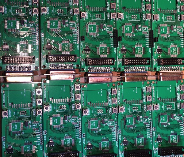
All the Floppy Emus are built by hand, by me, with a regular soldering iron. It’s a fairly labor-intensive process, and with orders averaging about one per day, it’s monopolized most of my free time for the past month. I’ve been building boards in small batches of three to five at a time, updating the stock on the web page as new boards become available. This has created a pattern where Floppy Emu is constantly going in and out of stock, and I haven’t yet been able to get far enough ahead to keep a steady stock available. I guess that’s a good thing as it means there’s demand, but it would be nice if I weren’t always on the edge of running out.

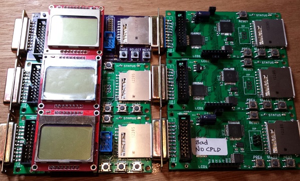
The 89% success rate is pretty bad. Or maybe it’s reasonable for a hand-assembled electronics item, but throwing 11% of the hardware in the trash is a frustrating and expensive way to do manufacturing. Not only do I lose all the money that went into those failed boards, I also lose the hours it took to assemble and test them. This is an area where I really need to improve. The defective boards failed in various ways that I couldn’t diagnose or repair. Some of them almost work, but exhibit occasional failures when reading or writing. Others are nothing but scrap.

I’ve looked into having an assembly shop build a batch of Floppy Emus, but I probably need to purchase 50 or 100 units at a time for it to be cost-effective. With a new manufacturer, there’s also a risk of some misunderstanding or error that would lead to delivery of 100 non-functional Floppy Emus, and I can’t afford that risk. There are also some elements that an assembly shop likely couldn’t accommodate with their standard process, like the edge-mounted DB-19 connector, and the LCD mounted on a separate module. So for the time being, Floppy Emus will continue to be hand-assembled.

Assembly is slow, and it’s not just the time spent soldering. Setting the AVR fuses, programming the chip, and adjusting the LCD contrast for each board takes a surprising amount of time. Just digging the next part out of the box eats a substantial amount of time too. With a dedicated work area I could leave all the parts laid out for easy access, but I have to get by with a small desk that’s also used for other purposes.

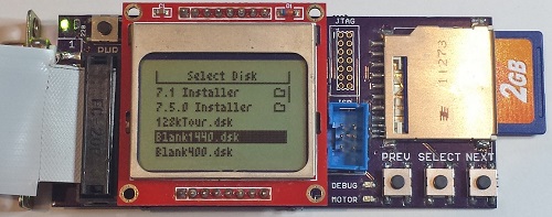
Each Floppy Emu is tested three times on three different computers: a 400K disk test on a Mac 512K, an 800K test on a Mac Plus, and a 1.4MB test on a IIsi. These aren’t just quick boot-up tests either: they’re read and write tests that fill an entire disk image, multiple times, using each of the two floppy connectors on the board. Each Floppy Emu goes through about 20 minutes of testing, but when testing multiple boards at once I can do one every 10 minutes with pipelining. That’s a lot of manual testing work, and it bloats the time per board beyond the actual assembly time. And of course if there’s a problem found during testing, more time is needed to troubleshoot and fix it.

Shipping and Handling

I used to think “handling” was just a bogus term used to rip-off buyers, but now I understand why the cost to ship something is not necessarily the same as the cost of postage.

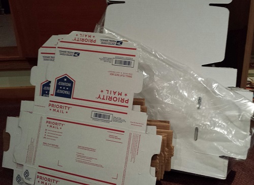
For USA shipments, it takes me about 10 minutes to prepare one Floppy Emu to be mailed. How can it take 10 minutes just to put something in a box? I didn’t believe it myself at first, but I’ve timed myself doing it often enough to accept it. The buyer’s contact info needs to saved, so I can contact him/her later if necessary. Then the Floppy Emu has to go in an anti-static bag, and the bag gets sealed. I have to assemble a box, fill it with foam peanuts, wrap the anti-static bag in bubble wrap, and cradle it in the peanuts. Then I need to print a packing slip and an instruction sheet, stuff those in the box, close it up, and seal it all with packing tape. Then I need to feed a sheet of label paper into the printer, log into the PayPal web site, purchase and print the postage, and stick it on the box. I have newfound sympathy for mail room employees.

For shipments going outside the USA, it takes about 15 minutes to prepare one Floppy Emu for mailing. For unknown reasons, PayPal will not sell postage for International First Class mail. I need to log into a separate account at the US Post Office Click-n-Ship site, and copy the pieces of the address one at a time from the PayPal data to the Click-n-Ship page. Instead of a single blank field for the address, Click-n-Ship forces me to break it up into separate form fields for first name, last name, street address, city, postal code, etc. Often these don’t match well with the way addresses in other countries are formatted.

If any letters have accents, the form validation fails, and I have to reformat it manually. Méndez Núñez must become Mendez Nunez. Sorry. This reminds me of some traffic signs in the area of California where I live. Many local place names are Spanish, and some signs for Cañada College have it as Canada College. When I first moved to the area, I couldn’t understand why the nation of Canada was sponsoring a local school.

I discovered that shipping materials cost real money! For USA shipments I can use the free Priority Mail boxes, but for international mailing I need to buy appropriate boxes, which must be purchased 50 or 100 at a time. Anti-static baggies, bubble wrap, packing tape, and shipping labels all cost money too. I hadn’t really considered this when I did my original cost estimates.

Once everything’s packed and ready to go, I have to bring it to the post office for mailing, which is about a 20 minute errand round-trip. Sometimes I can combine it with another errand, but I often find myself spending 20 minutes in the car just so I can mail a single Floppy Emu package. Post-9/11 paranoia means we’re no longer allowed to put packages in neighborhood mailboxes, but must take them to the post office and put them in the mail drop there. For international packages, you’re not even allowed to use the mail drop, but must wait in line to hand the package to a retail employee in person, even if the postage was already purchased online. Fortunately my local post office workers don’t insist on this rule, and told me that putting international packages in the mail drop is fine.

Between testing, packing, and visiting the post office, I’m averaging at least 30 minutes of labor per Floppy Emu above and beyond the time it takes to actually build it. Combined with the costs of shipping materials, that’s a significant amount of overhead I hadn’t planned for.

Parts Sourcing

Getting the parts needed to build each Floppy Emu has proven to be more challenging than I’d expected. I’m buying most of the parts from DigiKey, but the prices are constantly fluctuating, and sometimes it’s cheaper to buy certain parts from another vendor. It’s a bit of a puzzle, every time I refill my supplies. For most parts, the unit price is substantially cheaper when buying many of them vs buying a single one. I’ve been buying the majority of parts 10 at a time, but vendors other than DigiKey typically have higher minimum orders or steeper discount curves that force you into buying large quantities. I had to buy 73 of those DB-19 connectors!

Two other parts costs I neglected to account for are shipping and sales tax. These two combined add about 20% to my total cost of parts. In theory I could avoid paying sales tax by showing the suppliers a sales tax exemption certificate, but that would involve a layer of government red tape I haven’t wanted to mess with yet. It would also mean collecting sales tax when a California resident buys a Floppy Emu, which is something I really should be doing anyway, but would be a pain in the butt.

I discovered another hidden cost of parts sourcing too, and it’s one that wasn’t obvious at first. Say I’m building widgets, and each one needs a sprocket and a lever. If I buy 50 sprockets for $4 each and 50 levers for $3 each, then my total cost of parts is $7 per widget, right? Well, not exactly. It costs $350 to buy 50 sprockets and 50 levers, and I won’t recoup that cost until I’ve sold 50 widgets. If I do this repeatedly, on average at any given time I’ll have the parts for 25 unsold widgets sitting on my shelf. That’s a cost of $175 that I’ll never get back unless I quit the business after selling some exact multiple of 50 widgets. It’s like a security deposit, or worse.

The Sincerest Form of Flattery

The last of the business surprises was the theft of the Floppy Emu name. Another person (or company?) in Europe has started selling disk emulators using the Floppy Emu name for their product. I won’t link to it and lend it extra page rank points, but you can find it if you try. As far as I can tell, it’s a PC floppy emulator and not compatible with vintage Macintosh computers, so it’s not going to accomplish much except for confusing people.

Biz Summary

If you’re getting the picture that there are a lot of unforeseen costs and unexpected time sinks involved, you’re right. Don’t feel too sorry for me, though: even after all of this, I still make money from selling Floppy Emus. But with all the labor involved, it’s basically like I’ve invented a new part-time job for myself. It pays more than minimum wage, but not by much. :-)


Hardware

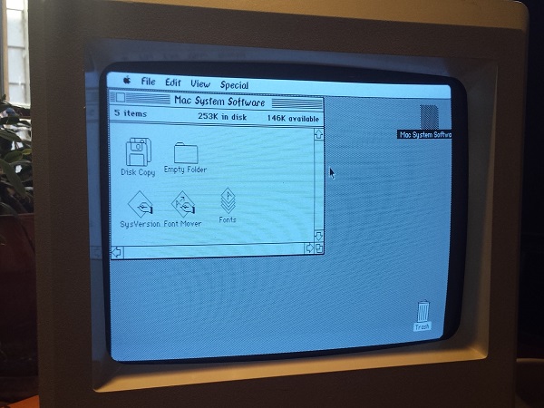
Enough of all this business stuff – let’s talk about what’s happening with the hardware! The good news is that Floppy Emu is working well in the wild, and I haven’t had any reports of major problems or incompatibility. The worst problem seems to be one I encountered myself: on my Mac 512K, maybe one in ten times the computer will fail to boot, and will show a Sad Mac error. I suspect this is because the drive speed emulation for the Mac 512K (and Mac 128K) is imperfect, and so the Mac sometimes freaks out when it thinks the floppy drive is rotating at the wrong speed. Newer Macs don’t use the drive speed signal and so don’t run into this problem. On the other hand, maybe it’s just something flakey about my 512K.
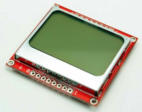
LCD

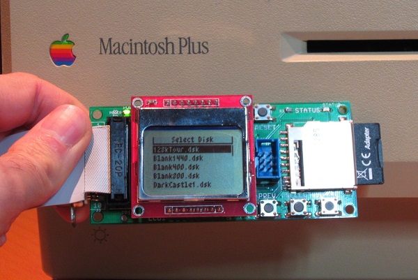
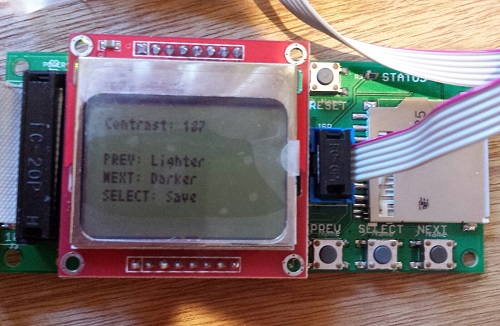
The LCD has been a source of headaches. About 10% of the LCD modules I’ve purchased have been defective in some way: damaged screens or dead pixels. That’s annoying, but the bigger headache has been varying contrast between LCD modules. Using the same software contrast setting, some modules show nice crisp text, some are washed out, and some are nearly solid black. I think it has something to do with how the LCD glass is mounted on the module, as I can usually change the contrast by pushing on the glass with my finger.

For the LCDs that don’t look good with the default contrast setting, I’ve been making custom firmware versions with a different contrast value, so every Floppy Emu that ships should have a nice display image. This isn’t a good long-term solution, though. It’s time consuming, and the customized firmware will be lost if the user ever applies a firmware update. People can make their own custom firmware, but it’s a hassle. What I probably need to do is add a manual contrast adjustment feature to the firmware, with the selected contrast value stored in EEPROM. Then everybody can tune the contrast exactly how they want it.

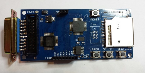
The revision 1.1 board that’s shipping now was designed to backlight the LCD, and the LCD modules have backlight LEDs built-in. After doing a few samples, though, I decided it looked better without backlighting. The backlight highlighted imperfections in the display glass, and gave it a washed-out look. All the Floppy Emus that are now shipping have the backlight disabled, but for people who really really want backlighting, they can add a 220 Ohm resistor at location R5 to enable it. A future board revision will have a through-hole footprint for R5 instead of a surface-mount footprint, to make it a little easier for modders.

Future Development

Time permitting, I hope to continue development of the Floppy Emu firmware. Some early adopters discovered that Floppy Emu works with the Apple IIgs, but it’s not as simple of a setup as I’d like. It works when the Floppy Emu is connected to the pass-through board of a real 3.5 inch Apple external drive, but not when Floppy Emu is connected directly to the IIgs. I’m pretty clueless when it comes to all things IIgs-related, so I’m not sure what’s going on, but I hope to find out.

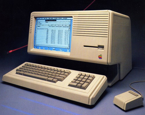
According to what I’ve read, it should also be possible to make Floppy Emu work on a Lisa – the precursor to the Macintosh. This would require a firmware change, since Lisa disks have essential data in the “tags” section of each sector, but the Macintosh doesn’t use tags and Floppy Emu ignores them. This may never happen, though, since the Lisa community is such a small audience of potentially interested people. I’m not ready to plunk down thousands of dollars for a Lisa just to test it out.

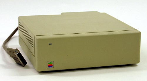
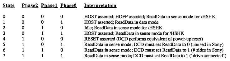
The most exciting thing on the horizon is HD20 support. The HD20 was a very early Apple hard drive from before the introduction of SCSI, and it connected to the external floppy port. In the past, several people have suggested HD20 emulation as a possible new feature, and I’ve always said it was impossible. But some new documentation that’s recently come to light suggests it may be possible after all – so Floppy Emu could emulate a 20 MB hard disk instead of an 800K floppy. In fact, it might even be possible to emulate hard disks larger than 20 MB. Unfortunately only a few early Macs have HD20 support in ROM, so it wouldn’t be a universal solution, but it would be great for those Macs that support it. It looks like HD20 emulation would involve a near total re-write of the Floppy Emu firmware, though, so don’t expect to see it next week!


LCD Contrast Adjustment in Firmware

$
0
0

Floppy Emu uses a generic LCD that’s a clone of the display in the Nokia 5110 phone. It’s a nice little bitmapped display with a good range of configuration options, including the ability to set the display’s contrast level through software instead of with an external resistor. Unfortunately there’s a huge variability in contrast response from one LCD to the next, and even the same LCD can exhibit contrast changes from day to day. I’m not sure if it’s due to temperature, fluctuating voltages, bad solder joints, or something else, but it makes it virtually impossible to choose one contrast level in the Floppy Emu firmware that will work well for all LCDs. Until now, I’ve been making a custom firmware build for each Floppy Emu that I assemble, with a hand-tweaked contrast level, but that’s a huge pain in the butt. No more!

Firmware 1.0L F11 introduces the ability to adjust the contrast level and save it to EEPROM. Now you can tune the contrast exactly how you like it. To adjust the contrast, hold down the SELECT and NEXT buttons while Floppy Emu is initializing (after pressing the reset button, or when first powering it on). After a few seconds, the contrast adjustment screen will appear. Press PREV and NEXT to tune the contrast level, and SELECT to save the contrast setting to EEPROM. Easy peasy lemon squeezy.

To apply this firmware update to your Floppy Emu hardware, download the firmware files, and copy the file femu.bin to your SD card. Then hold down PREV and SELECT while the Floppy Emu is initializing. This update only changes the AVR software (from 1.0K to 1.0L), the CPLD is unchanged (it’s still F11).

Happy contrasting!

Board Revision 1.2

$
0
0

Introducing Floppy Emu version 1.2: it’s blue, because blue makes it go faster! Buy yours now from the Floppy Emu product page.

Version 1.2 is a minor update that cleans up a few details. You may have noticed that the silkscreen labels on the version 1.1 boards looked a bit strange, with some overlapping labels and most parts labeled twice. That will teach me to submit my designs to the PCB fab without inspecting the Gerbers first! Version 1.2 corrects this, and makes everything much more readable.

More significantly, the pin assignments on the LCD connector have changed. The leftmost pin was 3.3V in version 1.1, but now it’s RESET, and the other pins have changed as well. This was done to accommodate a change that’s occurred in Asia where these LCD panels are made. About six months ago, I noticed that two versions of this Nokia-clone LCD were available for sale online, seemingly identical except for the order of the pins. Over time, LCD panels with the old pin layout became harder and harder to find, so I’ve switched to the new pin layout beginning with version 1.2. I had to replace my stock of LCDs, and was left with a few old-style LCDs I can’t use, but that’s the price of progress!

Did I mention that it’s blue?

You’ll also notice a through-hole resistor footprint labeled LIGHT, adjacent to the PREV button. This was added to make it easier for people to mod their boards to enable the LCD backlight. I think the backlight looks like poop, so I don’t enable it for the Floppy Emus I build. Some people really, really want the backlight, though, and this was meant to give them a way to do it. Unfortunately, it doesn’t work. The new-style LCD modules surprised me by reversing the polarity of the backlight LEDs, so the circuit I designed doesn’t work. Doh! Eventually there will probably be a version 1.3 to correct it. The vertical spacing between the two LCD headers is also a bit off, so that’s another point to address in a future version. But other than those minor headaches, I’m quite happy with this new version 1.2.

Mounting holes were added to the corners of the board in version 1.1, with the idea of supporting a case for the Floppy Emu. But to my knowledge, no one has made one yet. It should be simple to cut and drill two pieces of acrylic to act as top and bottom plates, and put them together with standoffs like a sandwich. It wouldn’t be a true case due to the open sides, but it would still look pretty spiffy. More advanced makers might use the mounting holes to anchor a custom 3D-printed case. At least one person was working on a custom case that looks like a miniature external Apple drive, but never quite got it to work. If you’ve got a cool case design, post it in the comments!


Emulating the Apple HD20

$
0
0

The Apple Hard Disk 20 (HD20) was an external 20 MB hard drive for the Macintosh, introduced in 1985. This was during the earliest days of the Mac’s history, before the introduction of SCSI support, so the HD20 connected to the Mac’s floppy port. Despite sharing the same DB-19 connector as a floppy drive, the HD20 used an entirely different communication method, making it something of a hardware freak. When SCSI support was introduced in 1986, external hard drive solutions quickly adopted the new standard, and the HD20 faded into obscurity.

During the long course of Floppy Emu’s development, several people have suggested that it might be possible to emulate the HD20 using the same hardware. In theory it should only require changes to the CPLD and AVR firmware, since the HD20 uses the same physical interface with the same pins as a floppy drive. But in practice, no documentation of the HD20 communication protocol existed, and reverse engineering it looked to be such a daunting task that it wasn’t worth it.

Circumstances changed last fall, when a couple of HD20 specification documents surfaced on the internet. Who knows where they came from – probably rescued from the bottom drawer of an ex-Apple engineer’s desk in a questionable release of company confidential information. But it’s hard to imagine anyone getting upset over documents nearly 30 years old, detailing a long obsolete peripheral for a long obsolete computer. The two most interesting documents are the specifications for “directly connected disks”, one dated March 1985 and a later revision dated May 1985. The DCD standard was planned to support a variety of device types, but ultimately the HD20 was the only product to ever use it. With these two documents and a careful examination of the HD20 driver routines contained in the Mac’s ROM, it looked like it might finally be possible to emulate the HD20.

Into the Abyss

So how does it work? First off, we can assume that raw data bytes are sent and received in serial fashion using NRZI encoding on the ReadData and WriteData lines of the floppy connector. While the DCD documents don’t specifically mention this anywhere, it’s a safe assumption because the floppy interface is powered by the Mac’s IWM chip (Integrated Wozniak Machine), which is hard-wired to send and receive data this way. So the main questions surround exactly what data bytes are sent and received, and when, and how the other lines on the floppy connector are used.

The DCD docs describe a state-based protocol that’s mercifully straightforward, compared to the oddities of the floppy drive interface. The Phase0, Phase1, and Phase2 lines on the floppy connector (sometimes called CA0, CA1, CA2) are used as a 3-bit state ID, to control the workings of a state machine governing Mac to DCD communications. At boot up, the Mac cycles through states 6, 7, and 5 in that order, checking the value on the ReadData line after each state transition. If it sees the values 1, 1, and 0, then it concludes that a DCD is connected to the floppy port, rather than a standard floppy drive.

HD20 communication is always a two-way exchange, with a command from the Mac followed by a response from the drive. From state 2 (idle), the Mac transitions to state 3 to indicate it wants to send a command. Seeing this, the DCD pulls /HSHK (the ReadData line) low to indicate that it’s ready to receive the command. The Mac then transitions to state 1 and sends the command, after which it transitions to state 3 to signal that it’s done. The DCD then brings /HSHK high again to acknowledge the end of the transfer, after which the Mac transitions back to the idle state.

When the DCD is ready to send a reply, while in the idle state, it pulls /HSHK low to indicate that it wants to send. The Mac then switches to state 1, and the DCD sends the reply bytes. After the last byte, the DCD brings /HSHK high again, and the Mac transitions back to the idle state.

Commands follow a fairly simple structure. A read command and response are shown above. The command begins with $AA, which functions as a sync byte and start of command marker. The next byte is the command id. In this case, $00 means it’s a read command. Following that are the number of 512-byte blocks to read, a three byte block address, a padding byte, and a checksum.

The reply looks similar to the command. Again there’s an $AA sync byte, followed by the command id. The command id in the reply is always the command id from the request plus $80, though I’m not sure the reason for this. After that is the sequence number of the block being sent, a status byte (zero means OK), more padding, the actual block data, and a checksum.

The HD20 carries over the concept of tag bytes that originated with the Apple Lisa, and that are also present (but unused) on Macintosh floppies. Each block has 20 tag bytes, so from a low-level point of view, blocks are essentially 532 bytes instead of 512, and 532 bytes of data will be returned in reply to a read request. The Mac throws away the 20 tag bytes, however, and only the last 512 bytes are treated as disk data. From the point of view of an emulator, only those 512 bytes need to be filled from a disk image file, and 20 bytes of zeroes can be prepended for the tags.

Because of the way the IWM works, the MSB of every transmitted byte must always be 1, so in effect there are only seven usable bits per transmitted byte. The DCD standard uses a 7-to-8 technique in which data is collected into groups of seven bytes, and then repackaged and transmitted as eight bytes with an MSB of 1 for every byte. This technique right shifts each of the seven bytes by one bit, chopping off the LSB, and setting the MSB to one. Then all of the chopped off LSBs are collected into an 8th byte. At the other end of the line, the receiver applies the reverse process to recover the original seven data bytes.

From Theory to Practice

That’s how it’s supposed to work, anyway, but there are many gaps and inconsistencies in the documents. One of the biggest concerns is that the March version of the doc differs in major ways from the May version. For example, the handshaking method described in the March doc is completely different than what I described in the previous section, based on the May doc. If there was that much change in the space of two months, it’s likely that the spec continued to evolve after that, and the May doc may not reflect the final version as it was eventually implemented.

Some important details just aren’t mentioned at all. What’s the checksum algorithm used? Nobody knows. An appendix also mentions a couple of dozen diagnostic commands, without describing what the parameters mean, or how the DCD should reply. Answering these kinds of questions requires a combination of educated guesswork, experimentation, and good old reverse engineering.

The code used by the Mac to communicate with the HD20 is contained in the ROM of the Mac Plus and other early Macs. Unfortunately this is raw 68000 machine language, so it’s difficult to read and understand what it’s doing. With the help of disassembler tools, the ROM data can be converted into 68000 assembly mnemonics, and symbolic names can be substituted for some known memory addresses, resulting in a code listing like this one:

L4772: MoveQ.L $4, D0
L4773: DBF D0, L4773
       Move.L D6, D0
       Add.L $810081, D0
       Move.B $-56, $400(A0)
L4774: Tst.B (A3)
       BPL L4774
       Move.B D0, (A0)
       Swap D0
L4775: Tst.B (A3)
       BPL L4775
       Move.B D0, (A0)

That’s not very instructive. But after long hours of studying and examining other nearby sections of code, some sense of structure does slowly emerge. For example, from looking at where A3 is set previously, I can tell that those Tst.B (A3) instructions are checking to see if the IWM is busy. And the Move.B D0, (A0) instructions are each writing a new byte to the IWM. Other clues are provided by the literal value $-56 appearing in the code, which when expressed as an unsigned byte is $AA – the sync byte. So what we have here is something that does a short busy loop, then adds $810081 to an unknown value from D6, and stores the 32 bit result in D0. Then it writes the $AA sync byte, waits for the IWM, writes the low byte of D0, waits for the IWM, and writes the high byte of D0. So it looks like it’s the preamble to sending a command to the DCD.

This is the kind of “deep in the weeds” analysis that’s needed to fill in the blanks for an emulation project. It’s something I’ve spent a lot of time doing for Floppy Emu and for Plus Too before that, so I’ve gotten pretty good at it, but I can’t really say it’s fun.

And a Progress Report

Armed with all this information, I began by hacking up the firmware on a Floppy Emu to identify itself as a DCD, and observe the proper handshaking rules for the various states. No data was actually sent or received. That was enough to get a noticeable reaction from the Mac: at bootup it froze for a long time, then when it finally did boot (from a SCSI drive), it complained that an attached disk was uninitialized and needed to be formatted. Then I wrote a simple test program to read arbitrary blocks from the DCD. The program always reported error -17 (driver can’t respond to this call). That was logical, but a little disappointing, as I could see from the ROM disassembly that there were many other more specific error codes that might be returned to give better feedback on what was and wasn’t working. I was hoping I might get an error like 64, no response received, or 33, timeout waiting for sync byte.

I spent a while tinkering with things, trying to get a more specific error than -17, but without success. I also tried using MacsBug to debug the HD20 driver routines while they were executing, but that appeared to create some new timing-related problems that messed things up even worse. Finally I decided to change course, and attack the other end of the problem by looking at what was happening on the Floppy Emu when the error -17 occurred.

I started with just displaying the current state number on the Floppy Emu LCD. I could see it go through states 6, 7, and 5 at bootup, just as the docs say it should. Then it went through states 2, 3, 1, 3, and 2, which looked like an attempted Mac to DCD command transmission. That seemed promising, so I leveraged the existing write code for Floppy Emu to try to collect the data bytes sent by the Mac, and display them on the LCD. That’s when I got the first payoff, as the received bytes were:

AA 81 B1 C1 81 80 80 80 80 80 FE

There was the $AA sync byte. And if you looked at the last eight bytes (beginning with $C1), it looked like a valid 7-to-8 encoding. Decoding those bytes yielded:

03 00 00 00 00 00 FD

That was command id 3 (drive status, according to the doc), with a bunch of padding and a checksum of FD. The sum of all the bytes mod 256 was 00, so that’s likely the checksum algorithm.

But wait, what were the second and third bytes for, 81 B1? Those shouldn’t have been there, according to the doc. Help! Truthfully I’m still not sure what those are, but after long examination of the ROM routines, I’m about 90% sure the first byte is the size of the data being sent, and the second byte is the size of the expected reply. Both sizes are expressed as a number of 7 byte groupings, then added to $81. In fact, the code that outputs those two bytes is the snippet I analyzed in the previous section.

So for the example above, the size of the data being sent was zero (no data payload for a drive status command), and the size of the expected reply was $30 groups of 7, or 336 bytes. Probably these size bytes were added to the DCD protocol late in the development process in an attempt to provide some amount of forward compatibility, so a device could gracefully handle an unknown command and send back a dummy reply of the correct size.

That’s where things stand today. With a little more experimentation, I’m hoping I can send back a valid drive status reply, or at least one that’s close enough to generate a more specific error code than -17. Then things will start to get very interesting.


Supply Chain Snafu

$
0
0

nokia-5110-lcd

Where and how do you find the parts needed to build your hardware? Selling Floppy Emu on a small scale has introduced me to the difficulties of managing a supply chain, and I’ve discovered it’s more difficult than it looks. Doing it wrong means higher costs, more risk, and a danger of running out of key parts at the wrong time. Due to my own poor planning, Floppy Emu has been stuck at “out of stock” for far too long, and I can’t even say for certain when it will be back.

Choosing a vendor from whom to buy parts seems like it should be easy: just use a search engine like Octopart to find the vendor with the lowest price. Sadly it’s not that simple. Some guy on eBay may have the lowest price, but how can I know if his parts are good quality, or if they’re recycled, relabeled, or even counterfeit? Is the savings enough to be worth the risk? And then there are “overstock” vendors like Arrow, Avnet, and Verical, who often have very good prices but require minimum orders of 100+ parts. Are they worth it?

Even if it’s clear which vendor is best for a specific part, it becomes less clear when all the parts are considered together. Floppy Emu is built from about 15 different types of parts, and if I ordered each one from a different vendor, the combined shipping costs from all those vendors would kill me. It’s a balancing act, and it’s often necessary to buy a part from a vendor whose price isn’t the best, so I can combine it with other parts in the same order from that vendor.

Mapping all this out is a pain, but at least it only needs to be done once, right? Wrong. The vendor prices are constantly changing, and less commonly the minimum order sizes change as well. So every time I go to order more parts, I have to start the analysis over again.

I struggle the most with determining how many parts to order. Virtually every vendor has a sliding price scale, where the per-part cost decreases as the number of parts ordered goes up. So there’s an incentive to make orders for large numbers of parts to drive down the average cost, but there’s also a risk. If I order 100 ATMEGA1284 microcontrollers, and then interest in Floppy Emu dries up, I could be left with $1000 worth of useless chips sitting on a shelf. But if I order them 10 at a time, I’ll not only be paying more per chip, I’ll also be reordering nearly every week and risking running out of parts if demand temporarily spikes up.

Out of Stock

My current problems are due to Floppy Emu’s LCD display. In mid-January I thought I had two boxes of LCDs remaining, when in reality I only had one. When I discovered the truth, I only had about six LCDs left. I placed an order for more LCDs on January 29, from the same Chinese vendor I’d used in the past. But then Chinese New Year hit, and nothing happened for a week. The package finally shipped on February 6. Meanwhile, I ran out of LCDs on February 8 and put Floppy Emu into “out of stock” status.

My last order from this vendor took 10 days to arrive from China, so I expected the new LCDs to appear around February 16. But that day passed with nothing in my mailbox, nor the next, nor the next. Time ticked by. As I waited, I accumulated enough Floppy Emu back orders so that the new supply of LCDs would already be nearly exhausted by the time it arrived, so I placed a second order for even more LCDs.

When I checked back on the first order, I saw the vendor was now quoting 25 to 30 working days for delivery. What?! That’s like a month and a half! I’m not sure if this was a change in policy, or the 10-day delivery time I had earlier was just an outlier, but they were now giving me an estimated delivery date of March 7-15. Somehow the second LCD order was estimated to arrive earlier, on February 28 to March 6, despite being ordered three weeks after the first LCDs and being shipped by the same method. And there’s no tracking info on either shipment, so there’s nothing to do but wait.


Viewing all 167 articles
Browse latest View live