![]()
![Apple_II_badge]()
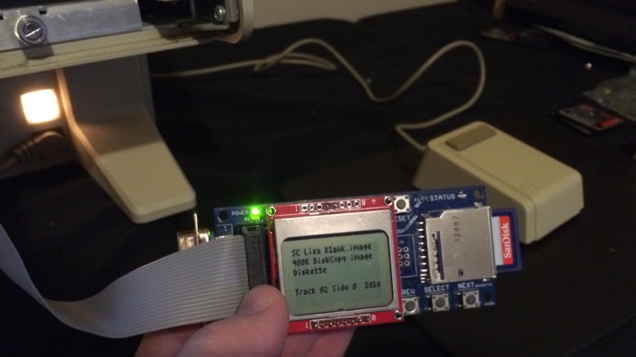
I’ve begun looking into the possibility of Apple II disk emulation with the existing Floppy Emu hardware. The recent research project into Lisa floppy emulation turned out well, so why not do it again with another vintage Apple computer? A cursory check of connector pinouts suggests it’s at least theoretically possible, though it would require major changes to the emulator firmware. But Rome wasn’t built in a day, so let’s start.
There are a confusing number of different Apple II family models and floppy drives. Some are 5.25 inch drives, and some are 3.5 inch. Some use a 19-pin D-SUB connector, and some use a 20-pin ribbon connector. Because of these differences, “Apple II disk emulation” won’t be a single emulator mode, but several different ones depending on the Apple II model and disk image being used.
This summary of Apple floppy drive models gives a nice overview. For the purposes of Apple II emulation, the drives can be organized into three categories: the venerable Disk II and its cousins (Disk IIc, Unidisk 5.25, Apple 5.25, Duodisk 5.25), the SmartPort-based Unidisk 3.5 (A2M2053), and the Apple 3.5 external drive (A9M0106).
Disk II Emulation
![apple-iie]()
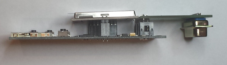
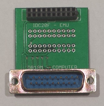
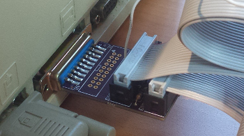
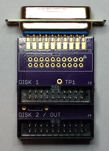
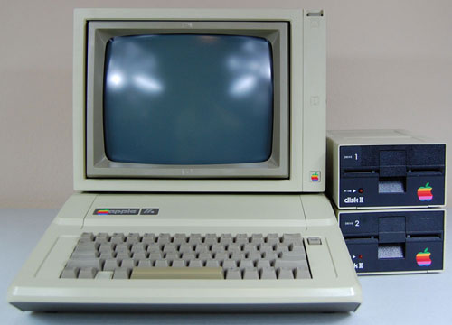
Emulation of low-density 5.25 inch Apple floppies would be useful for the Apple IIe and earlier models. These computers used a Disk II controller card in an internal slot. The controller card has two 20-pin ribbon connectors, each of which can be connected to a Disk II drive. The pinout of this 20-pin connector is almost identical to the pinout of Floppy Emu’s 20-pin connector. So with the right firmware (five words that gloss over a huge amount of work), you could plug a Floppy Emu directly into the controller card and emulate a Disk II floppy drive. Or plug two Floppy Emus into each of the two controller card connectors, and emulate two drives. With a custom multi-ended cable, it might even be possible to emulate two drives with a single Floppy Emu.
| Pin |
Floppy Emu |
Disk II Controller |
| 1 |
GND |
GND |
| 2 |
PHASE0 |
PHASE0 |
| 3 |
GND |
GND |
| 4 |
PHASE1 |
PHASE1 |
| 5 |
GND |
GND |
| 6 |
PHASE2 |
PHASE2 |
| 7 |
GND |
GND |
| 8 |
PHASE3 |
PHASE3 |
| 9 |
N.C. |
-12V |
| 10 |
/WREQ |
/WREQ |
| 11 |
+5V |
+5V |
| 12 |
+5V |
+5V |
| 13 |
N.C. |
+12V |
| 14 |
/ENABLE |
/ENABLE |
| 15 |
N.C. |
+12V |
| 16 |
RD |
RD |
| 17 |
N.C. |
+12V |
| 18 |
WR |
WR |
| 19 |
N.C. |
+12V |
| 20 |
PWM |
WPROT |
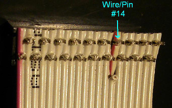
The only obvious mismatch is at pin 20. On the Mac, PWM is an output that controls the rotational speed of the 400K floppy drive. But on the Apple II, WPROT is an input that indicates whether the disk is write-protected. So depending on the emulation mode, pin 20 on Floppy Emu would need to behave like either an input or an output, and that’s a problem. The Emu uses a CPLD to interface with the computer, and it’s easy enough to modify the CPLD to change a pin between acting as input or output. But in practice this would be problematic and dangerous.
Let’s say your Floppy Emu board was configured in Apple II mode, and you plugged it into your Mac, with the intention of switching it to Mac floppy mode. But before you could even access the mode select menu, you’d have two outputs fighting each other on pin 20, possibly damaging the Floppy Emu, the Mac, or both. You could work around this problem by connecting the Emu to and Apple II and then switching to Mac floppy mode from there, but it would be an awkward and error-prone process. Some kind of passive adapter could probably solve this problem, with an inline resistor on pin 20, but I’d prefer to find a solution that doesn’t require extra hardware.
To complicate matters a bit more, there are two different standards for Apple 5.25 floppies. DOS 3.2.1 and earlier stored 113.75 KB per disk, 256 bytes per sector, 13 sectors per track, 35 tracks per side. But DOS 3.3 and later used a more efficient GCR encoding to store 140 KB per disk, 256 bytes per sector, 16 sectors per track, 35 tracks per side. As I understand it, this change also required a new version of the Disk II controller card. Was the newer one backwards compatible with the old format? Then there was ProDOS, which I believe used the same low-level format as DOS 3.3, but with a different filesystem. So Disk II emulation might actually involve two or three separate emulation modes, depending on the specific disk image being used.
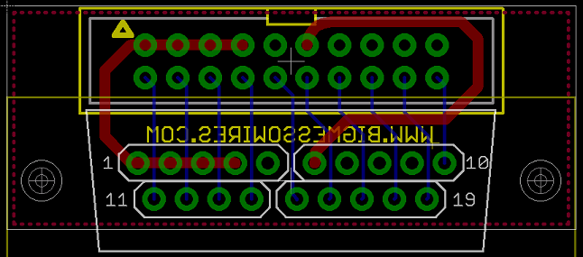
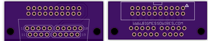
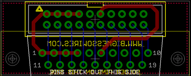
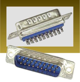
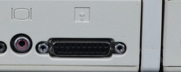
The later cousins of the Disk II switched to a 19-pin D-SUB connector instead of the 20-pin ribbon connector, but the drive itself remained basically the same. The 19-pin connector pinout matches Floppy Emu’s 19-pin connector just as well as the 20-pin, with no problems except the collision of PWM and WPROT on the same pin. That means it should be possible to connect a Floppy Emu in Disk II mode to an Apple II with a 19-pin controller card, or with a 19-pin external floppy port such as found on the Apple IIc.
SmartPort: Unidisk 3.5
![unidisk3.5]()
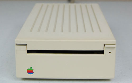
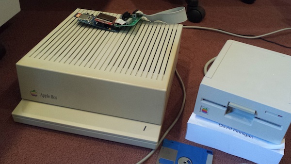
Next we have the Unidisk 3.5, an 800K floppy drive using the SmartPort communication protocol. Unlike the “dumb” Disk II, the Unidisk 3.5 was an intelligent device, communicating with the Apple II using a high-level request/response protocol that abstracted away the details of tracks and sides. From what little I’ve read about SmartPort, it sounds fairly similar to the HD20 protocol that I implemented a few months back for the Mac. It looks like there are already a couple of SmartPort-based disk emulators out there: UNIDISK and an SmartportCFA. That gives me hope that the SmartPort protocol wouldn’t be too difficult to implement.
Here’s where my understanding of things starts to get fuzzy, so if I say anything here that sounds incorrect, please let me know. It looks like the Unidisk 3.5 works on the Apple IIc, but only with certain ROM versions. There’s also a sub-model called the Apple IIc+, but I’m unclear if that’s anything more than a ROM upgrade, or what disk-related features the IIc+ offers over the IIc. The Unidisk 3.5 is also supported on the Apple IIgs, but it’s not recommended, because the performance is worse than can be achieved with non-SmartPort drives.
Did Apple ever sell other SmartPort drives, besides the Unidisk 3.5? I saw one source that mentioned SmartPort could support up to four drives per connection, and up to 32 MB per drive. If that’s true, could a SmartPort implementation on the Floppy Emu provide pseudo hard drive capability to the IIc and IIgs? I’m not sure.
How does the IIc or IIgs detect that a connected drive is a SmartPort drive, as opposed to a dumb 5.25 drive, or a non-SmartPort Apple 3.5 drive? Maybe it just sends a SmartPort request, and checks to see if anything responds. Or maybe there’s a pin that’s used to sense the drive type. The docs refer to a /3.5DISK signal on pin 4 of the 19-pin D-SUB, though I’m unclear how it’s used. More on this later.
Comparing the pinouts of the Floppy Emu 19-pin D-SUB connector with the Apple IIc and Apple IIgs, they mostly match up, but there are some noteworthy differences. There’s some disagreement about the published pinouts too, depending on which source you trust. I believe these are correct, and the Apple IIc+ is the same as the IIgs:
| Pin |
Floppy Emu |
Disk II |
Apple IIc |
Apple IIc+/IIgs |
| 1 |
GND |
GND |
GND |
GND |
| 2 |
GND |
GND |
GND |
GND |
| 3 |
GND |
GND |
GND |
GND |
| 4 |
GND |
GND |
GND |
/3.5DISK |
| 5 |
N.C. |
-12V |
-12V |
-12V |
| 6 |
+5V |
+5V |
+5V |
+5V |
| 7 |
N.C. |
+12V |
+12V |
+12V |
| 8 |
N.C. |
+12V |
+12V |
+12V |
| 9 |
N.C. |
/ENABLE2 |
/EXTINT |
/ENABLE2 |
| 10 |
PWM |
WPROT |
WPROT |
WPROT |
| 11 |
PHASE0 |
PHASE0 |
PHASE0 |
PHASE0 |
| 12 |
PHASE1 |
PHASE1 |
PHASE1 |
PHASE1 |
| 13 |
PHASE2 |
PHASE2 |
PHASE2 |
PHASE2 |
| 14 |
PHASE3 |
PHASE3 |
PHASE3 |
PHASE3 |
| 15 |
/WREQ |
/WREQ |
/WREQ |
/WREQ |
| 16 |
SELECT |
+5V |
N.C. |
SELECT |
| 17 |
/ENABLE |
/ENABLE1 |
/ENABLE |
/ENABLE1 |
| 18 |
RD |
RD |
RD |
RD |
| 19 |
WR |
WR |
WR |
WR |
There’s the same collision between PWM and WPROT that we saw previously, and I’m still not sure how best to resolve it. Then there’s this /3.5DISK signal on pin 4 of the IIc+ and IIgs, where others have an extra ground pin. What the heck? How is that used? Is it an input, an output, or both? The usage of pin 16 varies, but that shouldn’t cause a problem for the Emu, assuming the firmware is changed appropriately.
The biggest discrepancy is at pin 9, which isn’t physically connected on the Floppy Emu board. This is some kind of external interrupt on the IIc, which I think can be safely ignored. But on the other systems, pin 9 is used to select the second drive in a two-drive configuration. That means the Emu will be limited to emulating only a single drive, which is probably fine since that’s all it does anyway.
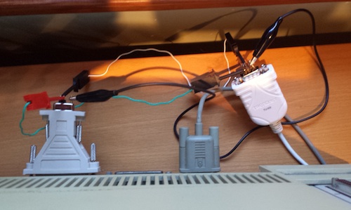
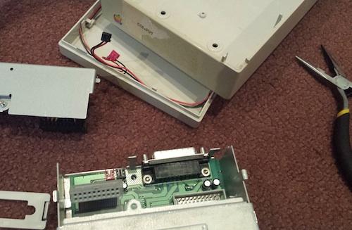
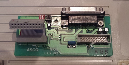
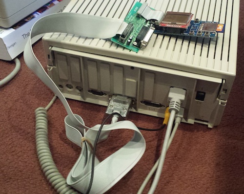
Incidentally, if you have a Unidisk 3.5 drive, you can remove its drive mechanism and substitute a Floppy Emu in its place. Combined with the Unidisk 3.5′s internal daisy-chain board, this combination works today with the current firmware, on the Apple IIgs (and presumably also the IIc+) for 800K disk emulation. See Bryan Villados’ example on the Apple II Enthusiasts group.
Apple 3.5 Drive
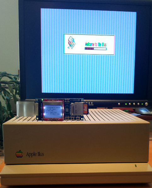
![appleiigs]()
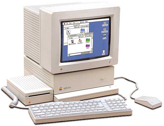
Last of the bunch is the Apple 3.5 Drive. Unlike the others, this drive functions on the Macintosh as well as on Apple II systems. It is not a SmartPort drive. How does that bit of magic work? I wish I understood it. Internally it’s the same Sony 800K mechanism that’s in the Unidisk 3.5 and in standard Macintosh floppy drives like the M0131, so the difference is only in the interface circuitry. I believe the Apple 3.5 Drive is supported on the Apple IIc+ and the IIgs, but it may also be supported on the standard model IIc – source seem to conflict on this point.
How does the computer know that an attached floppy drive is an Apple 3.5 Drive, and not a Unidisk 3.5 or other SmartPort drive, or a dumb 5.25 drive? I’m not sure, and the lack of documentation is frustrating. You can’t just plug a Macintosh floppy drive directly into a IIgs, so obviously there’s some difference in the way it identifies itself to the Apple II, but what is it? If I can find the answer, then I think the existing Floppy Emu firmware should work as-is for Apple 3.5 Drive emulation on the IIgs and IIc+.
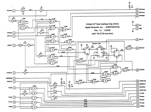
/3.5DISK Mystery Signal
![Funniest-schematic-ever-lg]()
The biggest mystery at the moment is how an Apple II system can detect what type of floppy drive is connected, and this /3.5DISK signal on pin 4 seems to be part of the answer. For detecting the difference between a dumb 5.25 drive and a SmartPort Unidisk 3.5, I think /3.5DISK must be irrelevant, because the standard model Apple IIc lacks the /3.5DISK signal but can still use a Unidisk 3.5 drive. Also, SmartportCFA successfully emulates a SmartPort drive, and doesn’t even connect pin 4. My guess is the computer sends some kind of SmartPort “init” command that will fail in a predictable way on a dumb 5.25 drive. Exactly how that works will have to wait for a deeper investigation of the SmartPort protocol.
Most likely, the /3.5DISK signal is used only for detecting the Apple 3.5 Drive. If the Unidisk can be detected by a SmartPort query, then /3.5DISK is probably only for distinguishing between an Apple 3.5 and a dumb 5.25 Disk II drive. That sounds easy enough, but when I start to look at the details, I quickly get lost.
First: is /3.5DISK 0 for 3.5 inch drives and 1 for 5.25 drives, or vice-versa? Most sources refer to it as /3.5DISK or 3.5DISK*, both of which imply it’s an active low signal where 0 means it’s asserted, so 0 should mean to enable the 3.5 drive. This is also consistent with the fact that the Macintosh has pin 4 permanently tied to ground, and in order for the Apple 3.5 drive to function on a Mac, it would need to interpret the 0 volts on pin 4 as the assertion of /3.5DISK. However, this discussion from comp.sys.apple2 says it’s actually the opposite: 0 enables the 5.25 drive and 1 enables the 3.5 drive. Maybe the writer is just mistaken, but I’m not so sure.
Second, and more fundamentally: is /3.5DISK an input, or an output? If the purpose is to detect what type of drive is connected, then it should be an input. None of the documentation I’ve seen actually specifies, but from a few odd comments and schematics, I’ve inferred that it’s actually an output. As best as I can determine, then, /3.5DISK acts more like a secondary enable signal than a drive type detection signal. When /3.5DISK is asserted, then the attached Apple 3.5 drives should respond, and when it’s not asserted the dumb 5.25 drives should respond. Combined with the /ENABLE1 and /ENABLE2 signals, this would provide a way to control two drives of each type, and four drives total (not counting SmartPort). But there’s a problem with this interpretation – the dumb 5.25 drives don’t know anything about /3.5DISK. They think pin 4 is a ground connection, so they’re not going to play along nicely. Obviously I’m missing something, because this just doesn’t add up.
The comp.sys.apple2 discussion that’s linked above further confuses the issue. It refers to /3.5DISK as “an extra enable” line, but also says “The Apple 3.5 drive uses this signal (on its daisy-chain connector) to sense whether a 5.25″ drive (or SmartPort drive?) is connected at the end of the chain.” In this context where it’s used to “sense” a drive’s presence, it sounds like /3.5DISK is an input. Maybe it’s actually some kind of clever circuit that’s both an input and an output, depending on the context.
A final question: what’s the difference between the Apple 3.5 drive and a standard 800K Macintosh floppy drive? The Apple 3.5 drive works on both an Apple IIgs and a Mac – how does it accomplish this? If the answer were only related to the /3.5DISK signal, and that signal was strictly an output from the IIgs, then a Mac 800K drive ought to happily ignore that signal and still respond to the /ENABLE1 signal, and work fine on a IIgs. But that’s not what happens, so there’s a piece of the puzzle I’m missing.