Quantcast
Channel: Floppy Emu – Big Mess o' Wires
Viewing all 167 articles
Browse latest View live

Clearance Sale: $79 Floppy Emu Model A

$
0
0

20150619_122211_resized

While supplies last, the Floppy Emu Model A is on sale at a clearance price of just $79. If you’ve been waiting to add one of these hard disk / floppy disk emulators to your Apple computer collection, now is your chance. The response to the new Model B has been great – maybe a little too great, and I need to close out the remaining inventory of Model A hardware. If you’re a Macintosh or Lisa user, or an Apple IIgs/IIc/IIc+ user looking for a Smartport hard disk, this is a great value! See the compatibility table on the order page and the Model B announcement for more details on Model A vs B differences.

If I were a savvier businessman, I might have waited to introduce the Model B until my inventory of Model A hardware was gone. It’s not quite the Osborne Effect, but introducing a new model that kills demand for the old model may not have been the smartest move. Fortunately for you, my loss is your gain! The good news is that interest in the Model B has been strong. In the past I typically made about one sale per day, but recently it’s been much busier. This was the scene heading to the post office after the 3-day MLK Day weekend:

box-tower

The Model A is the original Floppy Emu design that’s been featured here at BMOW for over a year. It emulates a classic Macintosh HD20 hard disk or 3.5 inch floppy disk, or a Lisa 3.5 inch floppy disk, or an Apple IIgs/IIc/IIc+ Smartport hard disk, or an Apple IIgs/IIc/IIc+ 5.25 inch floppy disk. Many people have purchased both a Model A and a Model B, to get a dedicated drive for each Apple computer in their collection. Don’t miss this chance to pick up a Model A at a great price!


SD Card SPI Initialization

$
0
0

floppy-emu-error-10-5

What happens when two devices share the same SPI bus? With a good design, each device is enabled one at a time for use of the bus, and they coexist without problems. With a bad design, SPI communication that’s intended for one device is sent to the other, leading to confusion and buggy behavior. In the Floppy Emu disk emulator, the SPI bus is shared between an SD card and an LCD display. As it turns out, it had a bug like this that escaped notice for almost two years, with the occasionally flaky behavior wrongly attributed to bad SD cards, faulty boards, or the phase of the moon. Doh!

The symptom was a “No SD card” message, with error code 10:5, when using a few specific models of SD card. During startup, the Floppy Emu firmware was sending SPI commands to the LCD to draw an image, then sending SPI commands to the SD card to initialize it. In rare circumstances, the initial communication with the LCD was confusing the SD card, leaving it in a state where it refused to respond to any further commands until the power was turned off and on. This caused the Emu to think no card was present. The problem didn’t always happen 100% of the time, and it appeared to depend on the electrical characteristics of each board and anything attached to it. But for certain models of SD card, it happened so consistently that the only remedy was to use a different SD card.

My solution was simple: initialize the SD card before doing any LCD communication. Grab the new firmware with the fix here:

floppy-emu-1.0R-F13Mac Floppy
hd20-0.7E-F14.5Mac Floppy + Hard Disk and Lisa Floppy
apple-II-0.1K-F7Apple II, for Model B
apple-II-0.1K-F6Apple II, for Model A

 
SPI Mysteries

You might wonder how a problem like this could have gone unnoticed for so long. Looking back over two years of support emails, I only found four problem reports that could be retroactively attributed to this issue. In each case, the person was able to get things working by trying a different SD card, so we chalked up the problem as a damaged or flakey card. It was only recently that I received two reports from people who’d tried multiple cards, all of which failed with the “No SD Card” message and error 10:5. Following up on their hardware, I bought two suspect 16 GB cards (1, 2), and confirmed that they both just plain didn’t work. Ouch. I’ve now verified that the new firmware gets both these SD cards working, and also received confirmation from some other users that the new firmware gets their troublesome cards working too.

So what exactly was the problem? The frustrating answer is that I don’t really know, and my description of the issue intentionally glossed over some important details. It’s true that the LCD communication somehow confused certain SD cards, but I can’t explain why.

Floppy Emu SPI Bus

Here’s a simplified diagram of Floppy Emu’s SPI bus. The LCD and SD card are independently enabled by separate, active low signals LCDE and SDE. Because the AVR microcontroller operates at 5V, all its outputs are passed through a 74LVC244 buffer to step them down to 3.3V for the LCD and SD card (the 3.3V signal MISO is an output from the SD card, and doesn’t need level conversion). SDE also has a 10K ohm pull-up resistor to +5V, to ensure that the SD card is disabled when the AVR isn’t actively driving the signal, during reset and microcontroller startup.

The only way it should be possible for the SD card to be confused by LCD communication traffic is if SDE were asserted at the wrong time. Looking at the schematic and the firmware code, I just don’t see how that’s possible. The pull-up resistor ensures that the SD card will be enabled if the AVR isn’t actively driving it. And once the AVR does begin actively driving it, it drives SDE high (unasserted) until it’s ready to begin communication with the SD card. So the card should be disabled during the initial LCD communication, and should ignore whatever is happening on the SPI bus.

If I weren’t so lazy, I would put a scope on the SPI bus, and verify that SDE is truly unasserted during LCD communication. But I’m lazy, and didn’t do that.

A few hints point to an electrical problem. With some cards, the 10:5 error occurred more often when I had an AVR programmer attached to the SPI bus, even if the programmer wasn’t active. And with those same cards, seemingly trivial firmware changes would cause the error to appear and disappear. Sometimes I’d only get the error on half my attempts, so it wasn’t a deterministic problem.

Maybe poor circuit design causes a momentary noise spike on SDE, during startup and LCD communication. Ringing, ground bounce, or cross-coupling of signals might cause SDE to briefly appear asserted when it shouldn’t be, causing the SD card to try to interpret communications meant for the LCD. But if that were the case, I’d expect to see all kinds of similar communication errors with the SD card during normal operation.

Another possibility is that there’s something fishy going on with AVR pin PB4, which is also the SPI SS (slave select) pin. The datasheet mentions that there’s some special behavior related to this pin. But after reading that section of the datasheet, I don’t think that’s the cause.

My last theory is that the problem is caused by accidentally switching the SD card into 4-bit mode. SD cards can operate in three different modes: SPI, 1-bit SDIO, or 4-bit SDIO. The latter two modes use the card’s pins like a conventional data bus. I believe the details of 1-bit and 4-bit SDIO may be proprietary and require an NDA, and every hobbyist-made microcontroller project I’ve seen has used SPI instead.

The catch is that SD cards initially power on into 1-bit SDIO mode, and part of the SD card initialization process is to switch to SPI mode, which will remain active until power off. With the old firmware, during the Floppy Emu’s initial LCD communication, the SD card was still in 1-bit SDIO mode rather than SPI mode. I don’t know anything about 1-bit SDIO mode, but maybe the chip select input is used differently in that mode, and my LCD communication was accidentally triggering a switch to 4-bit SDIO mode. As I understand it, once switched to another mode, that mode will remain active until power off, which is consistent with the “zombie SD card” behavior I observed with certain cards under the old firmware. Hmmm…

DB-19 Substitute, Take Two

$
0
0

20160223_143257 copy

BMOW’s product Floppy Emu needs a male DB-19 connector to mate with vintage Apple computers, but these connectors haven’t been manufactured in decades. For two years I’ve been scraping by with “new old stock” DB-19’s from warehouses around the world, but that supply has almost completely dried up. I recently found a few hundred more, but it’s clear that the end will come sometime in 2016. To prepare for the worst, I’ve been working on a design for a DB-19 substitute. After more experiments, today I decided that this path has reached a dead end.

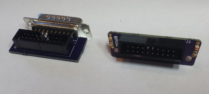
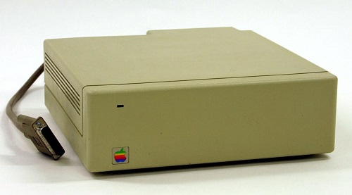
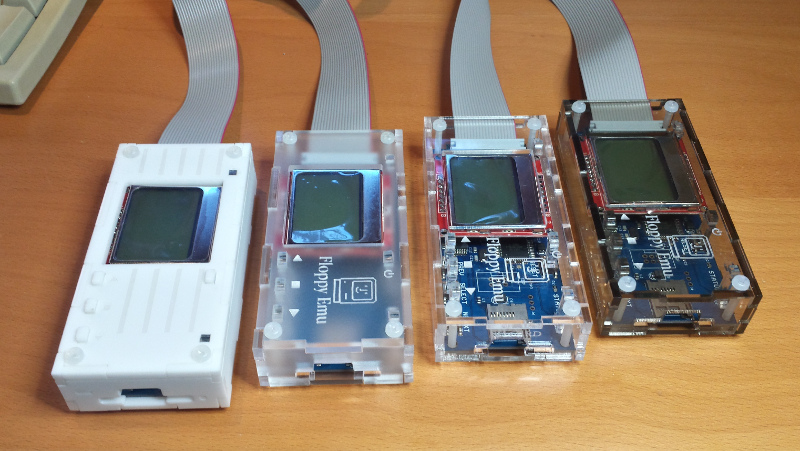
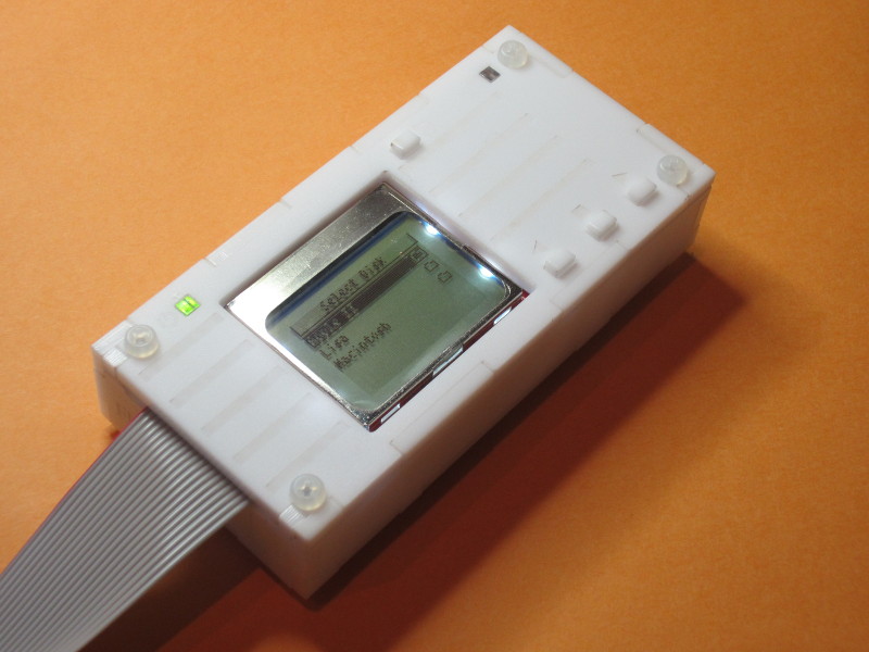
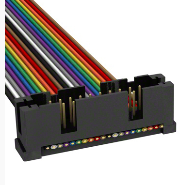
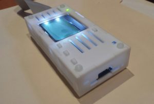
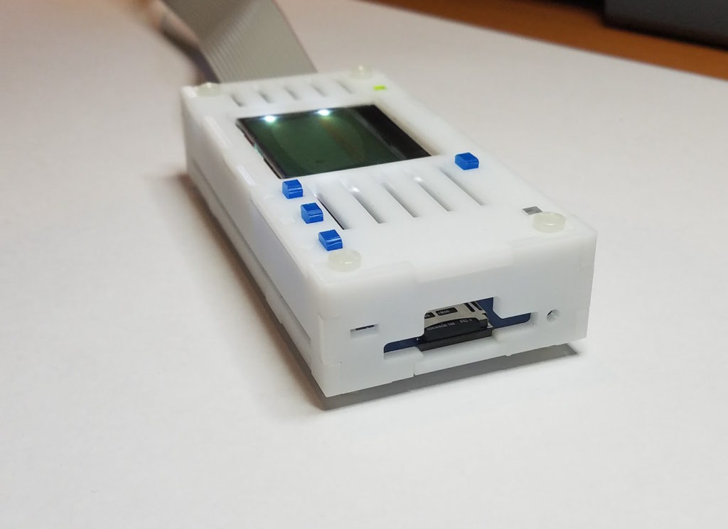
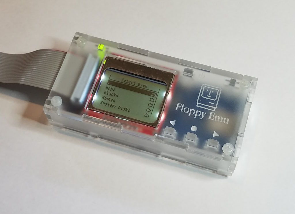
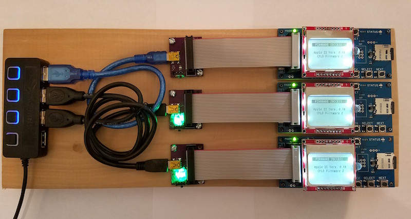
The current DB-19 adapter for Floppy Emu is shown at left, in the photo above. It consists of a small PCB with an edge-mounted male DB-19 at one end, and a 10×2 shrouded header connector at the other end. A ribbon cable plugs in to the 10×2 header, and the DB-19 plugs into the computer’s external disk port, and everything is great.

 
Designing a Substitute

The basic idea of a DB-19 substitute is to replace the male DB-19 with sections of 0.1 inch male header arranged in a DB-19 pattern, while keeping everything else more or less the same. I first explored this idea a year ago, and the prototype worked reasonably well, but had its share of problems. The 0.1 inch pin spacing didn’t quite match the 0.109 inch spacing of a D-SUB connector, and it put square pins into round holes. Without a surrounding shield, it was too easy to misalign the substitute connector while plugging it in, so I added two rectangular LEDs as structural elements to serve as mechanical guides. It sounds dodgy, but it passed some quick tests on several different Apple computers. Then I put the prototype away in a drawer, and didn’t think about it again.

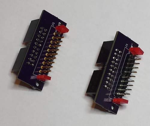
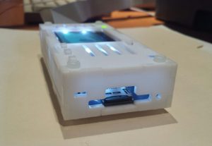
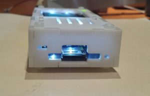
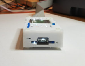
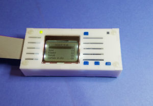
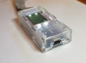
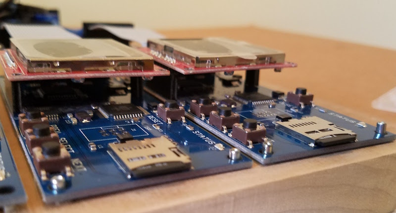
This week I received a new PCB for what I hoped would be the final DB-19 substitute design. I shrunk the overall size of the PCB, and gave it a trapezoid shape with rounded edges to invoke the spirit of a real D-SUB. I split up the 0.1 inch headers into a larger number of smaller sections, so the average offset from the nominal 0.109 inch spacing was reduced. And taking a popular suggestion from the first prototype, I made the LEDs into more than mere mechanical guides – now they light up! It’s a pretty cool effect. A side-by-side comparison of this new DB-19 substitute with the current model DB-19 adapter is shown above, and a rear view of the same connectors is below:

20160223_143404 copy

 
Quality Control Failure

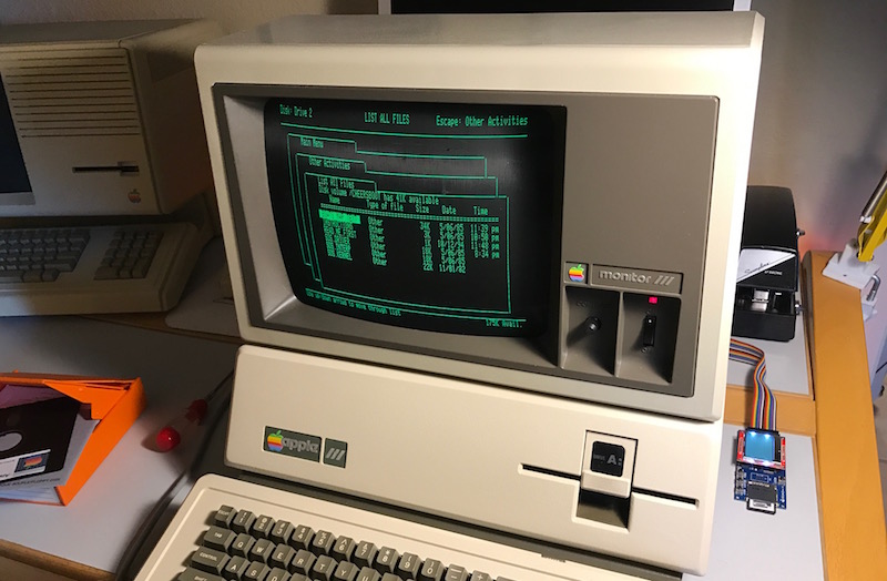
The new DB-19 substitute passed all my initial tests, and everything was looking good. But once I started testing more carefully, I realized that the connection wasn’t solidly reliable. It worked 100% of the time on my Mac Plus, Apple IIgs, and a borrowed Apple IIc+. But when plugged into the daisy chain connector of an Apple 3.5 Drive, it only worked about half the time. And when plugged into an Apple IIc, it never worked, unless I pushed on the connector with my finger during disk I/O. Ugh. At first I thought maybe this new DB-19 substitute had some new problem, but when I tested last year’s version more carefully, it had the same issues.

I think there are several things preventing this from working reliably. While putting square pins into round holes sounds crazy, I think that’s the least of the problems. What’s more significant is that the diagonal length of each pin’s cross section is probably slightly different than the diameter of the round pin that’s supposed to be there. Combined with the slight misalignment of some pins, I believe this leads to weak or no contact for those pins inside the female connector. I don’t know if the female’s interior has flat wipers, or a true round receptacle. Maybe different models of Apple computer have different receptacle designs. It doesn’t seem like a good idea to rely on that.

The other problem is the vertical height of the whole DB-19 substitute assembly. The current DB-19 adapter has only a male DB-19 at one end, with a height of about 3/8 of an inch. But the new, reduced size DB-19 substitute assembly has a PCB directly behind the pins, with a height of about 5/8 of an inch. For most Apple computers, the extra height is no problem. But for a few systems with recessed disk connectors, the extra bulk bumps into the plastic above the recessed connector, preventing it from being fully plugged in. On an Apple IIgs, it just barely fits. On the daisy chain connector of an Apple 3.5 Drive, it doesn’t fit.

 
Alternate Ideas

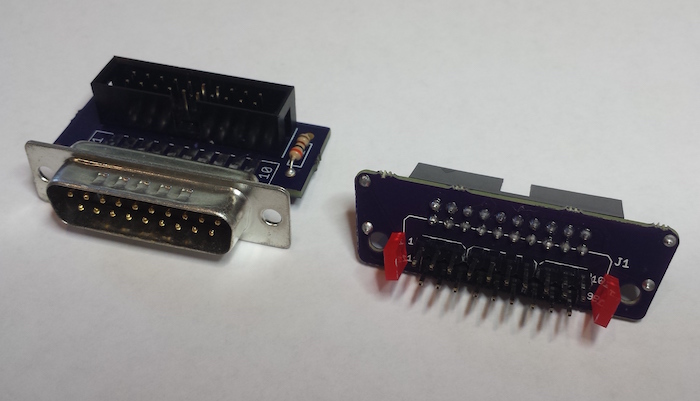
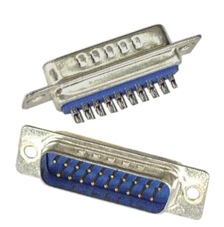
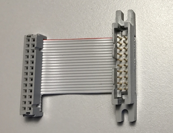
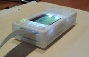
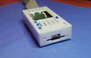
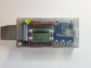
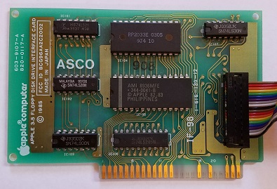
What to do? I’m probably going to abandon the idea of using 0.1 inch male header, as it just doesn’t seem reliable. Another option is to use 19 individual D-SUB crimp pins, soldered into the DB-19 substitute PCB. I built one of these last year, and it’s shown at left in the photo below, along with the first generation of the 0.1 inch male header substitute.

DB-alternates

The version with the D-SUB crimp pins is definitely more reliable, but it’s a nightmare to assemble. Crimp pins aren’t designed to be soldered into a PCB like this, and to prevent solder bumps on the pin side from shortening the effective pin length, the pins need to be soldered from the “wrong” side of the board using an ugly technique. Individual pins won’t stay straight while soldering, so a female DB-19 must be used as a jig during assembly. And when it’s done, the crimp portion of each pin must be cut off with shears. The current DB-19 adapters are factory assembled with a mostly automated process. This crimp pins design would require a cumbersome manual process, driving up the cost, if the factory was even willing to do it. And the problem with the height of the assembly would still remain.

The other option is to find a D-SUB factory that could manufacture new male DB-19 connectors. I checked into this last year, and it looked like a tough road. Negotiating that kind of manufacturing deal is difficult for someone like me, with no industry contacts or big name credibility. Most places didn’t even respond to my emails. From those that did, it looked like setup costs would be around $10,000 before they could make even a single part. Given the small scale of my business, that’s not realistic. I’d have to buy a virtual lifetime supply of DB-19 connectors, and hope that Floppy Emu sales continued on pace through 2030 or so.

This just became my new #1 problem. I’m going to work on brainstorming other solutions involving D-SUB crimp pins or other round pins, and also make another set of inquiries for manufacturing new DB-19 connectors. The clock is ticking…

 
February 23 Addendum

After mulling this over for a while, I’m coming to the conclusion that I should get new DB-19 connectors manufactured, even if it costs $10,000. It’s the only solution I’m confident will work reliably. Everything else I can think of is a trade-off of quality for cost, and nobody’s going to be happy if I switch to a new style of DB-19 substitute that’s not always reliable or that has trouble fitting certain computers.

The cost of manufacturing new connectors is high, but the alternatives aren’t free either. I priced out one possible alternative involving an empty DB-19 male housing and 19 crimp pins, and it would cost about $5 per connector including the increased labor cost to assemble it. At the current sales rate, I’d be spending about $2000/year for a solution that’s inferior to a real DB-19. Compared to that, $10,000 doesn’t seem quite so unreasonable. The other alternatives I described earlier would be cheaper to build, but seem to have reliability problems, so they’re not really viable.

I’ve been using the number $10,000 as a rough figure, but it may be less than that. Assuming the best quote I received a year ago is still valid, it would be roughly $8000 to get 10,000 DB-19 connectors manufactured and delivered. That’s about one third of the total profit I made from all BMOW product sales last year. So it’s a big number, but not completely out of the question. I don’t need 10,000 DB-19 connectors, but I could probably resell some of those over the next few years and recoup $1000 or so of the manufacturing cost.

I’ve been talking with a person at IEC about splitting a new manufacturing run with them, which would help a lot if we can reach an agreement. Another possibility is to run a GoFundMe campaign and solicit donations to “save the DB-19″. If I could get enough vintage Apple enthusiasts to chip in $10 or so, it might make a significant dent in the manufacturing cost. Maybe I could put the names of the largest donors in the silkscreen of the adapter PCB.

At the end of it all, there’s just something cool about the idea of being the guy who resurrected the DB-19. Then the world can stop seeing sad pleas like this one. Maybe I’m insane, but that’s got to be worth something. :-)

The post DB-19 Substitute, Take Two appeared first on Big Mess o' Wires.

New Demo Video

Floppy Emu Firmware Update: Disk Automount

$
0
0

525-disk

By popular demand, I’ve added a new feature to the Apple II firmware for the Floppy Emu disk emulator: auto-mounting of the previous floppy disk image. If you turn off the computer while a disk image is inserted in the emulated floppy drive, the next time you turn the computer on, Floppy Emu will skip the menus and immediately load that same floppy disk image. This is a nice time saver if you tend to use the same disk image every time, but it’s buried in a sub-sub-directory on your SD card. It also makes it possible for an Apple IIc, IIc+, or IIgs to cold boot directly from a floppy disk image. Previously it was necessary to select the desired disk image from the Floppy Emu menu, then soft-reset the computer by pressing control-apple-reset.

apple-II-0.1P-F8Apple II, for Model B
apple-II-0.1P-F6Apple II, for Model A

I welcome your feedback on this change. While the convenience is undeniable, I’m not completely sure I like the new behavior. After the power is turned on, if the Floppy Emu is going to auto-mount a disk image, there’s a very short window of time during which it can be done. In order to auto-mount the floppy image quickly enough for the computer to boot from it, the Floppy Emu must skip the normal self test (smiley face logo) and version info screen (diagnostic info, and emulation mode selection). This may be a little confusing for people who are looking to verify their current firmware settings, or change the emulation mode. They can eject the auto-mounted disk to restore the normal startup screen flow. What do you think?

The post Floppy Emu Firmware Update: Disk Automount appeared first on Big Mess o' Wires.

DB-19 Group Buy

$
0
0

DB19MS-2

Holy cow, this is actually happening! After over a year of searching what seems like every warehouse and basement on the planet to scrounge for DB-19 connectors, I’m finally moving forward with the manufacture of new ones. As far as I’m aware, these will be the first new DB-19s made anywhere in two decades, since the days of the Macintosh II, Atari ST, and NeXT.

To make this work, we need to place a BIG order. Right now that looks like 10,000 pieces. If anyone else in the vintage Apple, Atari, or NeXT communities might be interested in joining this group buy for a minimum of 500 pieces or more, please contact me by Monday, March 21. For a male DB-19 with solder cups as pictured above, the price will be about USD $1.41 each, plus or minus a few percent depending on the final tally for shipping and other fees. If you’re interested in a smaller number of connectors, or just one, stay tuned. Other participants in the group buy will be selling individual connectors at retail once the manufacturing is done. More details soon…

Floppy Emu Firmware Update: Mac HD Menu

$
0
0

HD20

I’ve added a new feature to the Macintosh/Lisa firmware for the Floppy Emu disk emulator: a menu for selecting disk images while running in Mac hard disk emulation mode. This is the mode that enables Floppy Emu to function as an HD20-type hard disk with compatible Macintosh models, with disk sizes up to 2 GB. Previously the hard disk image was always taken from a file named “HD20.dsk” on your SD card. If you had a few different hard disk image files, and wanted to select the right one for a given situation, you had to put the SD card into your Windows/OSX computer and rename the desired file to HD20.dsk. While this wasn’t a common need, it was not especially user-friendly.

Get the new firmware here: hd20-0.7F-F14.5

With the new firmware, the first time you run it you’ll see a hard disk image selection menu. The name of the chosen disk image file is saved in EEPROM memory, and will be used for all future sessions. If you later want to choose a different disk image file, the NEXT button will return you to the selection menu.

After choosing a new disk image for hard disk emulation mode, the Mac needs to be turned off and on (Floppy Emu will prompt you to do this), or you need to press the Mac’s hardware reset switch. That’s because the Mac doesn’t expect HD20-type drives to be removable media, and doesn’t recognize when the disk has changed. Without a reboot, it will blindly continue as if the original disk were still present, leading to unpleasant results.

I welcome your feedback on this change. Let me know if you run into any trouble.

The End of Things

$
0
0

DB19MS

After predicting the end of the DB-19 connector supply for over a year, it’s finally happened. I recently sent my last stockpile of new-old-stock DB-19s to the board shop for assembly of more Floppy Emus. I have two left that I’m keeping as souvenirs, and that’s it. I’m sure there are still a few left somewhere in the world, hiding out in some obscure surplus warehouse, but they’ve become so difficult to find that they may as well not exist.

This also means the end of the Universal Adapter for Floppy Emu Model A, because building one requires a DB-19. I think I have two or three left, and when they’re gone that will be the end.

My stock of Floppy Emu Model B boards is nearly exhausted as well. I still have enough of the older Model A for the time being, but I expect the Model B will be sold out within a week. If all goes as expected, it will hopefully only be a short sell-out, since I’m expecting a new batch of Model B’s from the board shop in a few weeks. But later this year when those are all gone too, things will get interesting.

I’m working with a group of other vintage computer collectors and parts dealers to manufacture a large run of new DB-19 connectors. As far as I’m aware, these will be the first new DB-19s made anywhere in the world in the past couple of decades! More details on this soon.


DB-19: Resurrecting an Obsolete Connector

$
0
0

Oh man, this is good! You’re looking at the first DB-19 connector to be made in the 21st century:

post-1779-0-54317400-1462842644

This is a happy story about the power of global communication and manufacturing resources in today’s world. If you’ve been reading this blog for any length of time, then you’ve certainly heard me whine and moan about how impossible it is to find the obscure DB-19 disk connector used on vintage Macintosh and Apple II computers (and some NeXT and Atari computers too). Nobody has made these connectors for decades.

I’ve got a disk emulator product called Floppy Emu that attaches to an Apple DB-19 port, so I need a steady supply of these connectors to build my hardware, and that’s a problem. Over the past couple of years, I’ve scrounged what seems like every warehouse and basement on the planet, and bought up nearly the entire world’s remaining supply of new-old-stock DB-19 connectors. My last few product batches included DB-19s from some very obscure international sources. It was clear I’d reached the end of the road.

This wasn’t a surprise. The DB-19 shortage first became obvious to me about a year and a half ago, when a manufacturing error forced me to replace all the DB-19 connectors in a batch of boards, and replacements couldn’t be readily found. Since then I’ve written a dozen times about the impending DB-19 doomsday. I also made several attempts to design a DB-19 substitute using a small PCB and suitably-arranged header pins, but while they more-or-less worked, I wasn’t satisfied with the result.

The specific part in question is a D-SUB DB-19 male solder cup connector, sometimes called DB-19P. It’s very similar to the more familiar DB-9 (old style serial ports) or DB-25, but with a different width to accommodate the different number of pins. “But wait!” says the well-intentioned blog reader, “this web site over here has DB-19P connectors for sale right now!” They may claim to have them, but trust me, they don’t. Electronics parts suppliers seem to make a habit of listing available items that aren’t actually available, whether out of laziness or as an intentional bait-and-switch, I’m not sure. But if you call them or try to actually order the parts, you’ll find they don’t exist.

 
Custom Manufacturing

About 15 months ago, I first started looking into the idea of manufacturing new DB-19 connectors. So here’s the thing – how do you go about having something like this made? I had no clue, and it took me over a year. How do you find factories that might possibly build something like this, and then how do you find a contact person to whom you can explain your needs? Almost all the manufacturers that I talked to blew me off, or wouldn’t even talk to me at all. The US-based manufacturers weren’t interested, or couldn’t do it. In the end, I went through Alibaba listings for companies that make other types of D-SUB connectors, and emailed several dozen of them to ask if they could make a DB-19. Only a few even replied, and only two said they could, both located in China.

The estimated cost was eye-watering – a minimum order size of 10000 pieces and a total cost well into five figures. I had naively assumed that somebody might still have old DB-19 molds they could reuse, or that DB-25 tools could somehow be easily adapted to make DB-19 connectors. Nope. I did a lot of research into possible alternatives like 3D printing or alternate materials, but nothing looked viable. And given the tiny scope of my disk emulator business, I couldn’t justify spending tens of thousands of dollars for making new DB-19s.

So nothing happened. A year passed, and the DB-19 shortage grew more dire still. I made another attempt at designing a DB-19 substitute, but wasn’t satisfied with the results. Out of options, I reluctantly circled back to the manufacturing idea again. I tried to calculate how many years of future sales it would take before I could earn back my investment, and it was a depressingly large number.

But just as I was getting discouraged, good luck arrived in the form of several other people who were also interested in DB-19 connectors! The NeXT and Atari communities were also suffering from a DB-19 shortage, as well as others in the vintage Apple community, and at least one electronics parts supplier too. After more than a year of struggling to make manufacturing work economically, I was able to arrange a “group buy” in less than a week. Now let’s do this thing!

 
Let’s Build It!

db19-mechanical-drawing-crop

Early on, it became clear they’d need more specific directions than simply “make it like a DB-9 but with more pins.” They wanted mechanical drawings and specifications for the part. Umm… They asked for information from my engineering department. Er… I was stumped by this for a short while, but then I found an old mechanical drawing of a DB-25. I photoshopped that sucker, edited some key measurements, and that was what they used for the very expensive mold-making process. I’m still kind of shocked that this actually worked.

Payment required wiring a Very Large Amount to a bank in Hong Kong – no PayPal accepted here. I’m sure the people at my bank thought I’d been duped by some kind of Nigerian 419 scam. Maybe it’s more common elsewhere, but transfers of this type are rare at US retail banks. In my case, it took the branch manager and 30 minutes of paperwork to get the transfer done.

Two months passed, and a round of prototyping. Progress was slow but steady, and I received updates from the manufacturer every few days. I kept waiting, eagerly anticipating this DB-19 bounty. At the end of May the product finally shipped, only to disappear into a US Customs black hole somewhere for a couple of days. Then at long last, after what felt like an infinite wait, I came home to find 10000 of these beauties stacked on my doorstep:

20160603_170816_resized

20160603_180001_Richtone(HDR) copy

20160603_175726_resized

For the moment at least, I have nearly the entire world’s supply of DB-19 connectors, stacked in my living room. I think I’m going to fill the bathtub and swim in them.

Next step: re-ship the majority of these DB-19 connectors to the other people in the group buy. They should start becoming available in small quantities at electronics parts suppliers in a couple of weeks.

Assuming Floppy Emu sales continue apace, I’ll eventually make back my investment in a couple of years. If not, it will at least make for a good story. :-) Now, let the retro-hardware celebration begin!

3D Printed Floppy Emu Case Experiment

$
0
0

3demuprint

My clear acrylic laser-cut case design for Floppy Emu looks sharp, but doesn’t match the visual style of classic Apple II or Macintosh systems. It’s also a bit tedious to assemble. A few people have suggested a Floppy Emu case that looks more like a retro 3.5 or 5.25 inch Apple drive, with Apple design details and a beige/white color. In that spirit, my friend Allan recently did some experiments with a 3D printed white case for the Floppy Emu, and the results look promising.

3D printing has the advantage of making any shape possible, instead of being constrained to interlocking 2D pieces with laser cutting. This enables the case to be built as just two pieces, rather than the six pieces needed for the laser-cut version. It also enables the button plungers to be built directly into the top plate, so they can’t fall out, making the whole thing easy to assemble. If you’ve struggled with the button plungers in the laser cut case, then you’ll appreciate this.

With 3D printing, it’s also possible to approach the appearance of a retro computer accessory. The case can be matte white, instead of glossy acrylic. 3D grooves and other small details can be modeled directly into the case, instead of being limited to 2D etching. Nobody will confuse it with a 1984 Apple peripheral, but at least it will be a lot closer.

I’ve mostly avoided 3D printing until now, because I’ve found it to be slow, expensive, and imprecise. Each one of these test prints required many hours of printer time and baby-sitting. The large time sink wouldn’t an issue if I used a commercial 3D printing service instead of home printing, but initial estimates are that a 3D printed case would cost perhaps 3x as much to manufacture as the current laser-cut case design. Maybe that would still be OK if the improved appearance and ease of assembly made it worth the extra cost to customers, but it’s a lot to ask.

Imprecision has been my biggest concern with 3D printing. Using my own budget printer, it seems half the prints I make come out badly deformed. Even the “good” prints always have a smooshed corner or deformed detail or other minor problem. It’s not terrible if you’re making a prototype for self-use, but I’m not sure it would be acceptable if making hundreds of them for sale to customers. Allan’s first case experiments showed some of the same types of deformities, although he was able to improve it somewhat in later iterations by making adjustments to his printer settings. Here’s an example of what I’m talking about:

20161130_114925_resized copy

Note how some of the grooves at left aren’t clean and even, and there’s a diagonal texturing across the whole surface that’s visible in some areas but not others. It’s hard to see in the photo, but the text and icons also have a slightly uneven appearance.

What surprised me was a test print made in Allan’s friend’s high-end 3D printer: it’s much more professional-looking, with very consistent print appearance across the whole case. That’s the print you see in the title photo above. I don’t know exactly what model of printer it was, or the cost, but I’ll try to find out. Here’s a close-up of the case from the better 3D printer, for comparison (click the image to see a high-resolution version).

20161130_130251 copy

A question to readers: would a 3D printed “retro-style” Floppy Emu case interest you? What features do you think would be most important? What do you think would be a fair price for something like this?

Laser-Cut Case Experiments

$
0
0

case-examples-800

While I continue experimenting with 3D-printed case designs for Floppy Emu, I’ve also been working on revisions to the existing laser-cut case design. These new laser-cut cases retain the same overall mechanical “box” as the original, but use a variety of materials, engraving, and opening cuts to give them new styles. Maybe one of these will become the new standard case, or an optional alternative. I’m interested to hear from readers about their opinions on these, so please leave a note in the comments below.

First, let’s review the existing case design that’s included in the Floppy Emu “deluxe bundle”. It’s transparent acrylic, and is great if you want to showcase the Emu’s inner chips and circuits. It looks like something an electronics fan would use with an Arduino or Raspberry Pi. The opening for the SD card is rounded, so you can reach in with your thumb and index finger to extract the micro SD card. The overall style is pretty spiffy, if I do say so myself.

clear-angle-800

clear-tilt-800

clear-front-800

One drawback of the clear acrylic case is that it’s practically invisible. It’s 100% transparent, like looking through glass, so the etchings on the case appear superimposed on the contents inside, creating a visual mash-up that’s sometimes hard on the eyes. It’s not a huge problem, but maybe a modestly-tinted acrylic case would be better than full transparent. This one is about 25% gray tinted, which is fairly subtle. The tint is obvious when it’s placed side-by-side with the clear case, but less noticeable when viewed by itself. The opening for the SD card on the tinted case is also slightly different, with a more squared-off look.

clear-vs-tinted-800

tinted-angle-800

tinted-tilt-800

tinted-front-800

The clear and tinted cases both have a gloss finish, giving them a sort of future-tech look. Unfortunately the gloss finish also makes fingerprints stand out clearly, which is a bit annoying. But even if you don’t mind a few fingerprints, not everyone loves the see-through look. If you enjoy showing off the geeky internals, it’s great, but some people prefer a functional case that looks more like a standard peripheral than a science exhibit. To that end, I made two more case designs using matte acrylic that’s mostly or completely opaque.

The first of these is built from a “matte clear” material, which really isn’t clear at all. It’s like frosted glass, and you can vaguely see a blur of color through it, but no details. If hiding the internals is what you’re after, this will do it. The matte material has a very pleasing texture, and doesn’t show fingerprints at all, so the case always looks clean. This case uses the same squared-off opening for the SD card.

frosted-angle2-800

frosted-tilt-800

frosted-front-800

The final case is built from a matte white material, and is my attempt to create something that looks more like a miniature Apple disk drive, using Apple’s “Snow White” design cues. It has a series of parallel grooves on the top plate, like the Apple IIc and IIGS and the Apple 3.5 inch external drive. The front opening even has a fake status LED and disk eject hole engraved in it, to make it resemble the front face of a real external floppy drive. The squared-off opening for the SD card is intended to give the feeling of the drive door from a 5 1/4 inch drive. This matte white case does a pretty good job of matching the style of the 3D-printed cases I posted last time, but is much faster and cheaper to make.

snow-white-angle-800

snow-white-rev-angle-800

snow-white-front-800

The major drawback of the matte white case is that the engraved areas are difficult to see. It’s white engraving on a slightly different shade of white background. You can see from the photos how subtle the grooves and other engraved details are. Depending on the angle of the light, they may be slightly more or less visible, but they never really stand out. The title photo displaying all four cases was actually photoshopped to make the top grooves stand out better, but the other images of the matte white case were not retouched. Overall I think it’s still a direction worth pursuing, but I definitely wish there were a way to give those engraved areas more contrast.

An alternative that just occurred to me is to actually cut the grooves and fake front details all the way through the material, instead of engraving them. This would certainly make them visible, but then you’d be able to see through to the Emu board inside. That’s not really accurate – you can’t see the Apple IIc logic board through the grooves in its case, for example, because there’s a second layer of plastic under each groove. Hmmm.

Floppy Emu on the Apple III

$
0
0

image6

The poor sad Apple III never gets much love. It wasn’t popular in its time, and had a short lifespan, but today it’s a sought after collector’s item. My Floppy Emu disk emulator for vintage Apple computers supports just about every machine Apple ever made except the Apple III – or does it? The enterprising Patrick Longinotti reports his success using the Floppy Emu to boot and run his Apple III system, using a custom cable and the stock Apple II firmware on the Emu.

How is this possible? The Apple III uses a 26-pin rectangular disk connector that’s physically incompatible with the 20-pin rectangular connector of other vintage Apple computers. But it turns out that Apple didn’t innovate much in their Disk III design, and the leftmost 20 pins on the Apple III disk connector are the same as the 20 pins of the standard Disk II connector (the remaining 6 pins are used for daisy chaining and auto-sense). All that’s necessary is an appropriate 20-to-26 pin adapter cable, and this guy on Tindie will make it for you!

disk3-adapter

Patrick reports that he’s been successful patching in the Floppy Emu as the Apple III’s internal drive, as well as using it as the sole external drive, and also daisy chaining it behind another Disk III external drive. It can be set up as drive 1 and boot the Apple III without any real floppy media, or set up as a higher numbered drive, and used after booting the Apple III from a real floppy in drive 1. According to Patrick, there occasionally will be errors, because the Disk III drives were either slower or faster than Disk II, but for the most part it works with very little issue. (Can anyone confirm this? I thought the drives were the same speed.)

Lots of Apple III software is available at apple3.org.

The only tricky part is getting the correct gender of connector on your adapter. I’ll admit that I’m confused by the Tindie seller’s description of the gender on his adapters, because they seem backwards to me. Maybe he’s referring to the gender of the connector shroud, which is the opposite of the actual pins? To be clear, this is what I mean by a female connector:

20-pin-female

And this is a male connector:

20-pin-male

The 26-pin connector on the Apple III logic board is male, as are the 26-pin daisy chain connectors on the Disk III drives. The Floppy Emu has a 20-pin male connector on its PCB. With a 26-pin female to 20-pin female adapter cable, you’ll be all set. The Tindie seller has these.

The female-to-female adapter cable isn’t necessarily the most convenient solution, however. Reaching the 26-pin male connector on the Apple III logic board is a major pain, because it involves taking apart the case, and removing the entire internal drive just to get access to the port. A simpler alternative is to disconnect the existing 26-pin cable from the internal Disk III, and then attach that cable to a 26-pin male to 20-pin female adapter cable to reach the Floppy Emu. The Tindie seller has these, but they’re only a couple of inches long.

A third alternative is a very short 26-pin male to 20-pin male adapter, combined with the existing 26-pin cable from the internal Disk III, and with the 20-pin cable that ships with the Floppy Emu. But nobody sells these.

In the end, you might need to make your own cable adapters. It’s not difficult, but if you experiment with homemade adapters, please be careful not to release the magic smoke from your valuable electronics!

New Firmware for Floppy Emu

$
0
0

middle-truncate

After a long period of hibernation, today I’ve released a set of firmware updates for the Floppy Emu disk emulator. These updates provide a few user interface improvements taken from customer suggestions over the past year, and also fix a couple of small bugs. Enjoy!

Ellipses in Long File Names – Don’t you hate it when you’ve got several disk images with very similar names, like Operating System Install Disk 1.dsk, Operating System Install Disk 2.dsk, and Operating System Install Disk 3.dsk? On the Floppy Emu’s built-in display, while browsing the contents of your SD card, the end of those long filenames were all cut off. You couldn’t tell which one was which when selecting a disk image from the menu. With today’s firmware update, the middle of those long filenames will now be replaced with an ellipsis, retaining the beginning and end of the name. Several people have been asking me for this feature for at least a year, so here you go.

Obvious Errors for Unsupported Disk Image Types – The Floppy Emu is always running in a specific emulation mode, like Apple II 5.25 Inch mode or Macintosh HD20 Hard Disk mode. When you’re browsing the contents of your SD card, the Emu knows which disk images are supported by the current mode, and which aren’t. The old behavior was to only display supported disk images and hide the others, but this seems to have confused everybody and left them wondering why their files disappeared. The new behavior is to list (mostly) all the files on the SD card, then show an error if the user selects something that isn’t a disk image supported by the current mode. In this case, you’ll see “disk image type is not supported in the current emu mode”.

Emulation Mode Highlight – Speaking of emulation modes, many people didn’t seem to realize that they exist, resulting in confusion when using the wrong mode or not knowing how to change modes. I can ask them to RTFM, but it would be nice if the UI made it more obvious. I’ve changed the Emu’s startup screen to display the current emulation mode right at the top, in inverse text, so hopefully it will now be impossible to overlook. I also fixed a subtle problem that affected people who switched from the Apple II firmware to the Mac/Lisa firmware: the Emu was defaulting to Lisa 3.5 Floppy mode after the firmware update. Quite a few people didn’t notice, and then couldn’t understand why floppy emulation didn’t work with their Macintosh. I’ve changed the behavior so it will now default to Macintosh 3.5 Floppy mode after the firmware update.

 
Get the new firmware here:

Macintosh and Lisa, for all Floppy Emu models: hd20-0.7G-F14.5
Apple II firmware, for Floppy Emu Model B: apple-ii-0.1R-F8
Apple II firmware, for Floppy Emu Model A: apple-ii-0.1R-F6

With any firmware update, there’s always a chance that I’ll accidentally break something, so please give me your feedback on whether these new versions work for you.

Snow White Case Experiments

$
0
0

It’s been a few months since I experimented with some alternative laser-cut and 3D printed case designs for the Floppy Emu disk emulator. The most popular case concept was the Snow White design, intended to complement the design style and color of mid-1980’s Apple computers. I’ve continued to experiment with the Snow White design as time permitted, and have finally arrived at a laser-cut Snow White case that I’m mostly happy with.

The laser-cut case is constructed from the same matte white acrylic that I used in the last prototype, which is about as close to vintage Apple coloring as I can get. But instead of subtle engraving for the case lines and other details, they’re now cut-outs that go all the way through. It’s hard to see in the photos, but the matte acrylic also has a slight texture to it. This creates a look that’s quite different from the smooth gloss normally associated with acrylic. I like it a lot.

With this prototype, I also tweaked the button plunger size very slightly, which should help give the buttons a tighter feel.

A question to readers: What do you think about the single grooves on the lower part of the sides? Good or bad? I was trying to echo the design of the top plate’s lines, but I’m not sure if plain solid sides would be better.


Working with a friend, I also did a few more experiments with 3D printed cases. These look attractive and are quick to assemble, but I concluded they’re just too slow and expensive to manufacture. I won’t be making any more 3D printed cases, but the remaining 3D printed prototype cases are available for sale if anyone would like one.


My goal is to create a polished Snow White case option that I can offer as an alternative for people who prefer this style. Meanwhile, I’m also working on some refinements to the standard case… more on that soon!

Now Available – New Enclosure Styles

$
0
0

After several months of experiments and refinements, two new enclosure styles for Floppy Emu are finally available for sale. First up is a Snow White case with the looks of a miniature external floppy drive. The grooved white laser-cut case mimics Apple’s vintage Snow White design style, made famous by machines like the Apple IIc. This case uses a matte finished acrylic that’s slightly textured, and will look at home alongside your other retro computer hardware. The buttons in bright blue provide an attractive visual contrast, adding an extra touch of class.

The second new style is frosted ice, and it’s replacing clear acrylic as the default case style for the deluxe bundle. The frosted ice case has a matte finish that resists fingerprints, and allows some light through without being totally transparent. It retains the “happy computer” etched logo from the earlier case style. Frosted ice has a retro-futuristic vibe like a 1960’s sci-fi drama. Danger Will Robinson!

Both new case designs incorporate a small but significant change to the button stalks, which are 0.3 mm taller than before. This should help minimize button slippage caused by variations in the acrylic material thickness.

You can find the new cases in the BMOW Store.


Bootstrapping Apple //c with Floppy Emu

$
0
0

Thanks to Floppy Emu fan Andru Luvisi for contributing a great trick for bootstrapping an Apple //c with Floppy Emu. The Apple II family computers can normally only boot from Disk 1, but when Floppy Emu is connected externally to a //c and configured in 5.25 inch emulation mode, it becomes a non-bootable Disk 2. Until now, the options for making Floppy Emu bootable on a //c were:

  • Switch the Emu’s emulation mode to Smartport hard disk, which is bootable
  • Boot from a real 5.25 floppy in Drive 1, and then access the Emu as Drive 2
  • Connect the Emu internally, in place of the real 5.25 inch floppy drive
  • Use an A/B switch cable to connect the Emu and the real 5.25 inch floppy drive internally

Andru has devised a method for booting the //c from the Floppy Emu while it’s connected externally and configured in 5.25 inch emulation mode. In other words, it’s a method for booting from Disk 2 – something that’s normally impossible. This is great for the scenario where you want to make a bootable ProDOS floppy, and you’ve got a Floppy Emu, but no real floppies with a bootable DOS. Now it’s possible to boot from the Emu externally, then put a blank floppy in the //c’s internal drive and copy ProDOS to it.

  1. Connect Floppy Emu to the //c’s external disk port, and turn on the computer.
  2. The //c will display a CHECK DISK DRIVE error.
  3. Select ProDOS v1.9 from the Floppy Emu’s disk selection menu.
  4. Press CTRL+RESET on the //c keyboard to get a BASIC prompt
  5. At the ] prompt, type CALL -151 and press RETURN
  6. At the * prompt, press CTRL+E, then press RETURN
  7. You’ll see a line of text like M=00 A=08 X=00 Y=00 P=00 S=B7.
    If the line of text begins with M, then type
    :0 E0 60 1 and press RETURN
    Else if the line of text begins with A, then type
    :E0 60 1 and press RETURN
  8. Type C60BG and press RETURN

The //c will immediately begin booting ProDOS from Drive 2!

Andru developed this method by examining code from Apple //c ROM version 255, which includes this feature natively as PR#7. The above monitor hacking makes it possible to do the same thing on other ROM versions of the Apple //c.

I was successful using this method with ProDOS v1.9, as well as with a few other utilities and games. Unfortunately most games won’t work using this method. They’re hard-coded to expect booting from Drive 1, so if you try this method they’ll start to boot from Drive 2, but then you’ll hear Drive 1 suddenly begin to grind away, and the game will freeze or display an error. Despite this limitation, booting 5.25 inch disk images from Floppy Emu as Drive 2 is still a very handy trick!

Snow White Case for Floppy Emu

$
0
0

The Snow White case for Floppy Emu is back in stock. This is my personal favorite: a matte white acrylic with a slightly textured surface, following Apple’s vintage Snow White design style, and with the looks of a miniature external floppy drive. It’s available with just the case, or as part of the Floppy Emu deluxe bundle.

The Programming Board

$
0
0

Behold the Floppy Emu programming board! Normally when you read “programming board” on this web site, you’d think of some circuitry on a PCB, but this time it’s a 3/4 inch thick plank of poplar wood. Ah, that kind of programming board!

Sometimes I need to reprogram a large number of Floppy Emus, and this tool makes the job much easier. My old method was to connect the Emus one at a time to an Apple IIgs, turn on the computer, push buttons to begin a firmware update, and then wait ~30 seconds for the update to finish. It was a slow and inconvenient process when dozens or hundreds of Emus needed reprogramming. With the programming board, I can slap down one Floppy Emu into a bracket, start the firmware update going, and then rotate to the next Floppy Emu. Everything is powered from a USB supply, and I use a hub with individual lighted switches to turn on power for each Emu bracket.

Updating three Floppy Emus in parallel is a big improvement, but there’s also another trick here that makes the process even better. With the old method on the IIgs, some fiddling with cables was necessary every time I connected or disconnected a Floppy Emu. Things would slide around on my desk, and I’d waste time getting the connectors lined up. The programming board uses metal pegs at each bracket to hold the Floppy Emu centered, so a short 4-inch ribbon cable can drop down perfectly aligned with the connector every time. Here’s a close-up of the alignment pegs:

If you’re wondering about those green lights on the bottom two power adapters, they’re not status indicators, but just simple power lights. I accidentally bought some high-brightness LEDs, and even with under 10 mA current they’re so bright that it’s irritating. They’re dazzling to the point of being blinding. Fortunately the LED in the top-most power adapter didn’t work due to my lousy soldering job. I covered the bottom two with 5 layers of paper, which cuts down and diffuses the brightness enough to be tolerable.

Floppy Emu Back in Stock

$
0
0

After a few weeks of scarcity, more Floppy Emu hardware is again available at the BMOW store, hot off the courier truck. It’s always my goal to keep a steady inventory available, but that’s proven more difficult than I imagined. The trouble isn’t surges in demand, or assembly problems, but just managing the supplies of all the materials involved.

To sell one Floppy Emu, I obviously need to have a main board in stock. But I also need the DB19 adapter board, which is a separate part. And I need 20-pin ribbon cables. And SD memory cards. And acrylic cases from the laser cutter. And padded mailers, boxes, bubble wrap, and postage labels. Sales grind to a halt when I run short of any of those supplies. To get them at reasonable prices requires buying them in bulk, with delivery times ranging from a few days up to two months. I can’t just drop into the corner store to buy more when I run low.

Maintaining those supplies efficiently can be challenging, and it’s not something I do very well. Real companies have automated inventory management systems that automatically order more parts as needed. I just glance into a box now and then, and maybe order more supplies if the pile looks small and I’m not busy doing something else. In this case I didn’t begin the hardware assembly process soon enough to account for the long lead time. I still had lots of hardware on hand when I reordered more, but it was all gone two weeks before the order was fulfilled. It’s one more thing I need to learn to do better.

Liron Support for Floppy Emu

$
0
0

Great news for owners of the Apple II Liron disk controller card: the latest Floppy Emu disk emulator firmware adds Liron support. This means that for the first time, it’s now possible to emulate 32 MB hard disks on an Apple II+ or IIe with the Floppy Emu!

The Liron is a “smart” disk controller for the II+ and IIe, using the same Smartport protocol as the Apple IIc, IIc+, and IIgs. It was originally designed to work with the Unidisk 3.5 inch floppy drive, but other Liron-compatible third-party external hard drives were later developed. With this new firmware, the Floppy Emu is able to emulate one of these hard drives, bringing an exciting new capability to the II+ and IIe.

Smartport emulation with the Liron card works nearly identically to the IIc, IIc+, and IIgs, as described in section 10.4 of the Floppy Emu manual. Connect the Emu to the Liron card, use the Emu’s menus to select Smartport mode, and populate your SD card with up to four disk images. These will appear as four virtual hard drives connected to your II+ or IIe.

Depending on your Apple II model and its version of the autostart ROM, the Liron-connected disk may or may not automatically boot when the power is turned on. If you have an older model that doesn’t autostart the Liron, type PR#7 to get things started (or PR#N if your Liron card is in slot N).

This is new firmware, so your help with testing is appreciated. If you tried the new firmware and it worked fine, please let me know. If it didn’t work, definitely let me know. Try it in Smartport mode with the Liron of course, but also try it with the built-in Smartport of your IIc, IIc+, or IIgs to verify it still works there too, and doesn’t interfere with other types of drives that are also present in the daisy chain.

Download the new firmware here:

Floppy Emu Model A – apple-II-0.1T-F16
Floppy Emu Model B – apple-II-0.1T-F18-modelB

Viewing all 167 articles
Browse latest View live


Latest Images